Setting up nativelink and simulation settings – Altera ALTDQ_DQS2 User Manual
Page 63
Clock
Description
outclk_3
125 MHz, used as half-rate clock.
outclk_4
500 MHz, used to drive the ALTDLL IP core. The minimum frequency for the
ALTDLL IP core for Stratix V devices is 300 MHz.
outclk_5
250 MHz, used to drive the full rate core clock.
outclk_6
125 MHz, used to drive the half rate core clock.
outclk_7
25 MHz, used as config_clk.
Note: lf the memory frequency is less than the ALTDLL IP core minimum frequency, then drive the
ALTDLL IP core at 2x or 4x of the memory frequency. The DQS phase settings decrease as well.
Setting Up NativeLink and Simulation Settings
To set up the NativeLink and simulation settings, follow these steps:
1. In the Quartus II software, on the Tools menu, select Options.
2. In the Options dialog box, under Category list, expand General and then select EDA Tool Options.
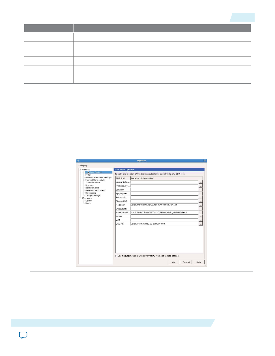
3. In the EDA Tools Options window, follow the settings as shown in the following figure:
Figure 25: EDA Tools Options Dialog Box
4. In the Quartus II software, on the Assignments menu, click Settings.
5. In the Settings dialog box, under the Category list, expand EDA Tool Settings. Click Simulation.
6. Enter the necessary NativeLink settings. The following figure shows an example settings. In this design
example, a testbench (tb.v) is provided together with other supporting files.
UG-01089
2014.12.17
Setting Up NativeLink and Simulation Settings
63
ALTDQ_DQS2 IP Core User Guide
Altera Corporation