Side read operation, Side write operation – Altera ALTDQ_DQS2 User Manual
Page 69
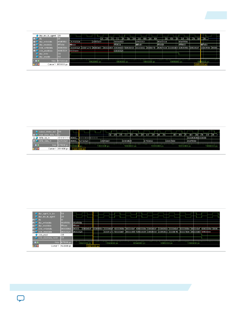
Figure 33: DQS Write Operation Waveform
Note: Before and after the DQS write operation, the
dq
signal is in Hi-Z mode to filter any unwanted
glitch on the bidirectional port.
The following figure shows the waveform after executing the topwave.do file. The
write_oe_in
signal is
held high throughout the five sets of valid
write_data_in
between 18.811 µs and 18.851 µs. Centre
aligned output data appears on
read_write_data_io
between 18.822 µs and 18.86 2µs. The
output_strobe_out
is a free running clock while the
read_write_data_io
is driven at Hi-Z when there
is no data transaction.
Figure 34: DQS Write Operation Waveform After Executing the topwave.do File
Side Read Operation
The side read operation is performed between 18.923 µs and 18.963 µs. The DQS agent sends data to the
DQS driver with the
side_readdata
signal. Data validation is carried out in parallel, by comparing the
side_readdata
signal against the content of the
check/i/o
(data which was written out during the DQS
write operation). If there is a mismatch, the software generates an error message.
The following figure shows the waveform for the side read operation.
Figure 35: Side Read Operation Waveform
Side Write Operation
The side write operation begins between 19.011 µs and 19.067 µs. The data written out from the DQS
driver is also stored in
check/i/o
.
UG-01089
2014.12.17
Side Read Operation
69
ALTDQ_DQS2 IP Core User Guide
Altera Corporation