A5 padtoinputregisterdelaysetting connects to the, Legend in figure 18 bit bit name description, Delayctrlin – Altera ALTDQ_DQS2 User Manual
Page 40
I/O Configuration Block Bit Sequence for Arria V GZ and Stratix V Devices
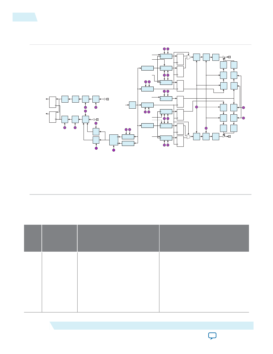
Figure 18: I/O and DQS Delay Chains for Arria V GZ and Stratix V Devices
1
0
DQ
D1
Delay
Chain
D1
Delay
Chain
A
B
Positive Edge
Read Data
Negative Edge
Read Data
D4
Delay
Chain
D4
Delay
Chain
E
F
DQS
Delay
Chain
T
DQS
T11
Delay
Chain
T11
Delay
Chain
R
To dqsenable
Port
To dqsdisablen
Port
DQS
Enable
Control
Q
S
From
dqsenableout
Port
Clock Phase
Select
Clock Phase
Select (0 Degree)
To
levelingclk
Port
To
zerophaseclk
Port
M N
X V
Output
Alignment
Clock Phase
Select (0 Degree)
Output
Alignment
W U
Output
Alignment
Output
Alignment
Negative Edge
Write Data
Positive Edge
Write Data
W U
Output
Alignment
1
0
Negative Edge
Write Data
Positive Edge
Write Data
X V
Output
Alignment
Output Enable
Signal
Clock Phase
Select
Clock Phase
Select (0 Degree)
I J
Leveling
Delay
Chain
Clock Signal
from Core
Clock Phase
Select
K L
Output Enable
Signal
O P
Output
Alignment
OCT Control
Signal
DQ
D5
Delay
Chain
D5
Delay
Chain
D6 OCT
Delay
Chain
D6 OE
Delay
Chain
D5 OCT
Delay
Chain
D5 OE
Delay
Chain
DQS
D5
Delay
Chain
D5
Delay
Chain
D5 OCT
Delay
Chain
D5 OE
Delay
Chain
D6 OCT
Delay
Chain
D6 OE
Delay
Chain
C
D
G
H
D2
Delay
Chain
D3
Delay
Chain
-
D6
Delay
Chain
D6
Delay
Chain
D5 OCT
Delay
Chain
D5 OE
Delay
Chain
D5 OCT
Delay
Chain
D5 OE
Delay
Chain
Use the combination of D1, D2, D3, and D4 delay chains for calibration. Use D1, D2, and D3 to delay
DQ, and D4 delay chain to delay DQS. D5 and D6 delay chains are the output delay chains.
The D2 and D3 delay chains are static input delay chains. The D6 delay chain is static output delay
chain. You can only set the settings in the Quartus II Settings File (.qsf) or the Fitter sets the settings
automatically based on the timing constraints. You cannot dynamically set the settings.
The following tables lists the I/O configuration block bit sequence, description, and settings for Arria V
GZ and Stratix V devices.
Table 12: I/O Configuration Block Bit Sequence for Arria V GZ and Stratix V Devices
Legend
in
Bit
Bit Name
Description
A
5..0
padtoinputregisterdelaysetting
Connects to the
delayctrlin
port of
the D1 delay chain to control the first I/
O buffer-to-input register delay chain
(D1).
Sets to tune the DQ delay (read calibra‐
tion) for DDR applications.
For delay values, refer to the “Program‐
.
40
I/O Configuration Block Bit Sequence for Arria V GZ and Stratix V Devices
UG-01089
2014.12.17
Altera Corporation
ALTDQ_DQS2 IP Core User Guide