Bandpass filters – EXFO IQS-12004B DWDM Passive Component Test System for IQS-500 User Manual
Page 418
Definitions and Calculation Methods
406
IQS-12004B
Bandpass Filters
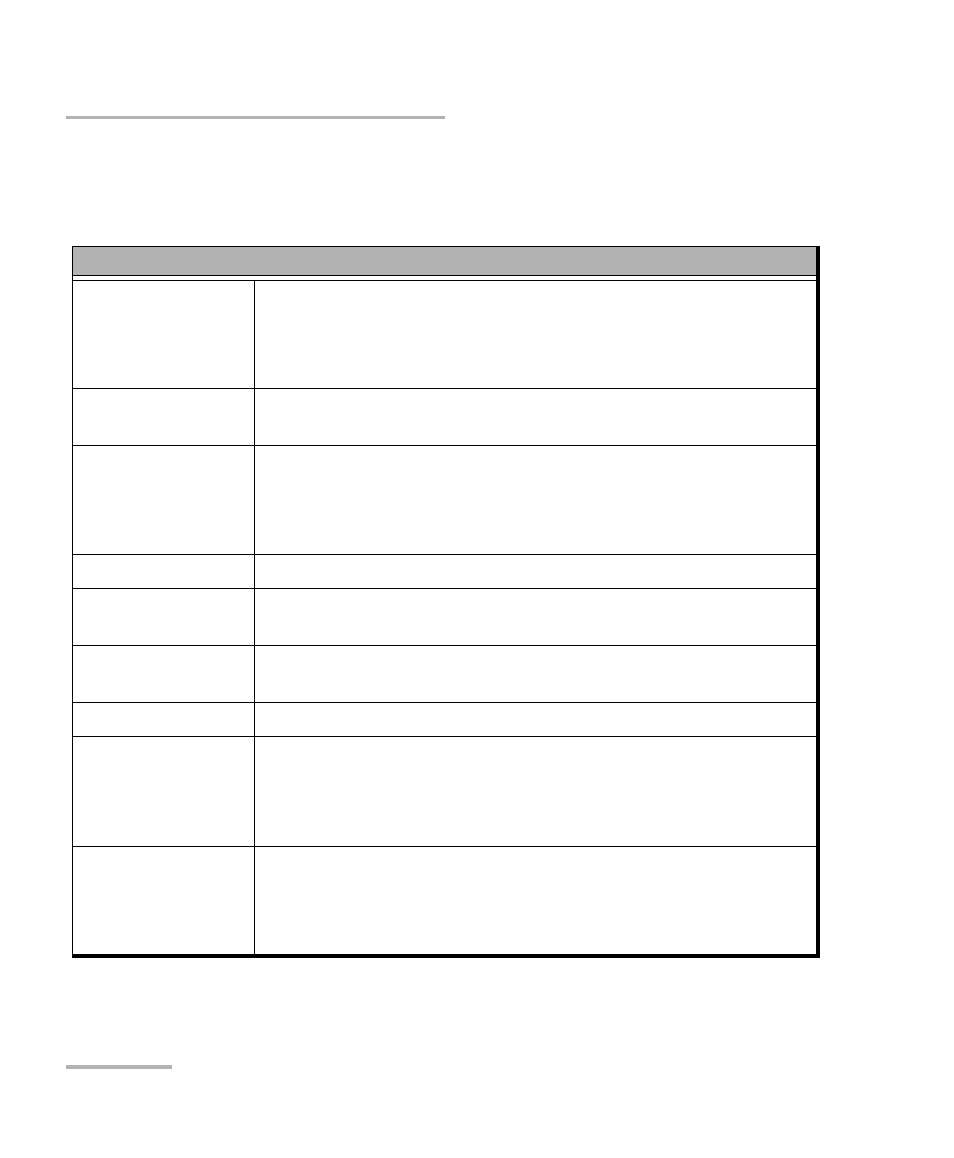
The following table summarizes the analysis made with bandpass filters.
Bandpass Filters
Central Wavelength X-dB center, where X is the dB level at which BW1 is measured
(see Central Wavelength (nm) on page 410).
When PDL is available, this is calculated using the average
attenuation.
Difference
The difference between the defined wavelength and the
measured central wavelength.
IL
Max attenuation over operating wavelength range (BW1) (see
Insertion Loss (dB) on page 410).
When PDL is available, this is calculated using the average
attenuation.
PDL (BW1)
Max PDL over the range defined by BW1.
PDL (CW)
PDL at the defined central wavelength (measured center for
Generic).
PDL (Central
wavelength ±x nm)
Max PDL over the range.
PDL (x to y nm)
Max PDL over the range.
BW1, BW2, BW3
The bandwidth at dB level relative to the peak transmission (see
Bandwidth (nm) on page 408).
When PDL is available, this is calculated using the average
attenuation.
Flatness
Delta attenuation across BW1 (see Flatness/Ripple (dB) on
page 411).
When PDL is available, this is calculated using the average
attenuation.