Mportant, Configuration of power meters, 25 installing hardware components – EXFO IQS-12004B DWDM Passive Component Test System for IQS-500 User Manual
Page 37: Dwdm passive component test system, Sync out sync in
Getting Started with Your DWDM Passive Component Test System
DWDM Passive Component Test System
25
Installing Hardware Components
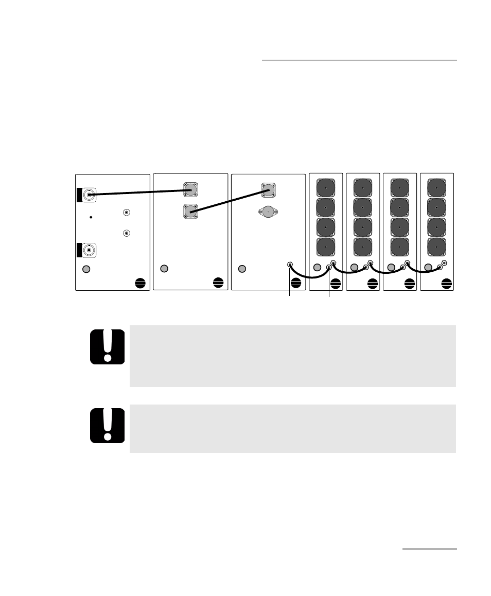
Configuration of Power Meters
The IQS-1643T power meters must be installed sequentially in the unit. Use
the short synchronization cables to connect power meters in the same
unit, and the long synchronization cables to connect power meters in
different units. It is also necessary to install a synchronization cable
between the IQS-9401 and the first power meter, as illustrated below.
I
MPORTANT
The power meters must be correctly installed and configured before
starting IQS Manager or before turning the unit on. If modules need
to be repositioned, you will have to restart the system.
I
MPORTANT
To keep the optical ports clean, ensure that protective caps are
always installed when the module is not being used.
SYNC OUT
SYNC IN
IQS-2600CT
ACTIVE
OUTPUT
MONITOR
OUTPUT
TRIG IN
TRIG OUT
Tunable Laser Source
IQS-5150
OUT
IN
Polarization State Adjuster
IQS-9401
OUT
IN
Wavelength Reference Module
Sync
Out
C1
C2
C3
EX
FO
N
TT
-FC
Sync
Sync In
4-Ch Power Meter
IQS-1600T
C4
Out
Trig
C1
C2
C3
EX
FO
N
TT
-FC
Sync
Sync In
4-Ch Power Meter
IQS-1600T
C4
Out
Trig
C1
C2
C3
EX
FO
N
TT
-FC
Sync
Sync In
4-Ch Power Meter
IQS-1600T
C4
Out
Trig
C1
C2
C3
EX
FO
N
TT
-FC
Sync
Sync In
4-Ch Power Meter
IQS-1600T
C4
Out
Trig