Power saving, Clock divide control, Power saving -6 – Maxim Integrated Ultra-High-Speed Flash Microcontroller User Manual
Page 98: Clock divide control -6, Figure 7-2. system clock sources -6
7-6
Ultra-High-Speed Flash
Microcontroller User’s Guide
Power Saving
The ultra-high-speed flash microcontroller is implemented using full CMOS circuitry for low-power operation. It is fully static, so the
clock speed can be run down to DC. Like other CMOS, the power consumption is also a function of operating frequency. Although the
microcontroller is designed for maximum performance, it also provides improved power versus work relationships compared with stan-
dard 8051 devices. These topics are discussed in detail in the following pages.
Clock Divide Control
The programmable clock divide control bits CD1 and CD0 (PMR, C4h) provide the processor with the ability to adapt to different crys-
tals and also to slow the system clocks, providing lower power operation when required. An on-chip crystal multiplier allows the ultra-
high-speed flash microcontroller to operate at two or four times the crystal frequency by setting the 4X/2X bit and is enabled by set-
ting the CTM bit to a logic 1. An additional circuit provides a clock source at divide-by-1024. When used with a 10MHz crystal, for
example, the processor executes machine cycle in times ranging from 25ns (divide-by-0.25) to 102.4µs (divide-by-1024) and main-
tains a highly accurate, serial port baud rate while allowing the use of more cost-effective, lower-frequency crystals. Although the clock
divide control bits can be written at any time, certain hardware features have been provided to enhance the use of these clock con-
trols to guarantee proper serial port operation, and also to allow for a high-speed response to an external interrupt. The 01b setting of
CD1 and CD0 is reserved and has the same effect as the setting of 10b, which forces the system clock into a divide-by-1 mode. The
ultra-high-speed flash microcontroller defaults to divide-by-1 clock mode on all forms of reset.
When programmed to the divide-by-1024 mode, and the switchback bit (PMR.5: SWB) is also set, the system forces the clock divide
control bits to reset automatically to the divide-by-1 mode whenever the system has detected externally enabled interrupts.
The oscillator divide ratios of 0.25, 0.5 and 1 are also used to provide standard baud rate generation for the serial ports through a
forced divide-by-12 input clocks (TxMH,TxM = 00b, x = 1, 2, or 3) to the timers. When in divide-by-1024 mode, in order to allow a quick
response to incoming data on a serial port, the system utilizes the switchback mode to automatically revert to divide-by-1 mode when-
ever a start bit is detected. This automatic switchback is only enabled during divide-by-1024 mode and all other clock modes are unaf-
fected by interrupts and serial port activity. See Power Management Modes for more details.
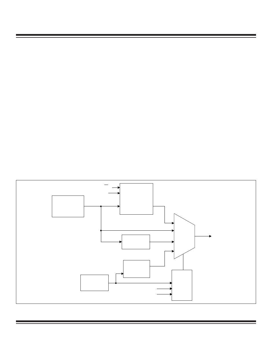
4X/2X
CTM
Crystal
Oscillator
Divide-by-1024
Ring
Oscillator
Clock
Multiplier
CD0
CD1
Selector
Ring
Enable
MUX
System
Clock
Figure 7-2. System Clock Sources
Maxim Integrated