Timer 2 control (t2con), Timer 2 control (t2con) -33 – Maxim Integrated Ultra-High-Speed Flash Microcontroller User Manual
Page 41
4-33
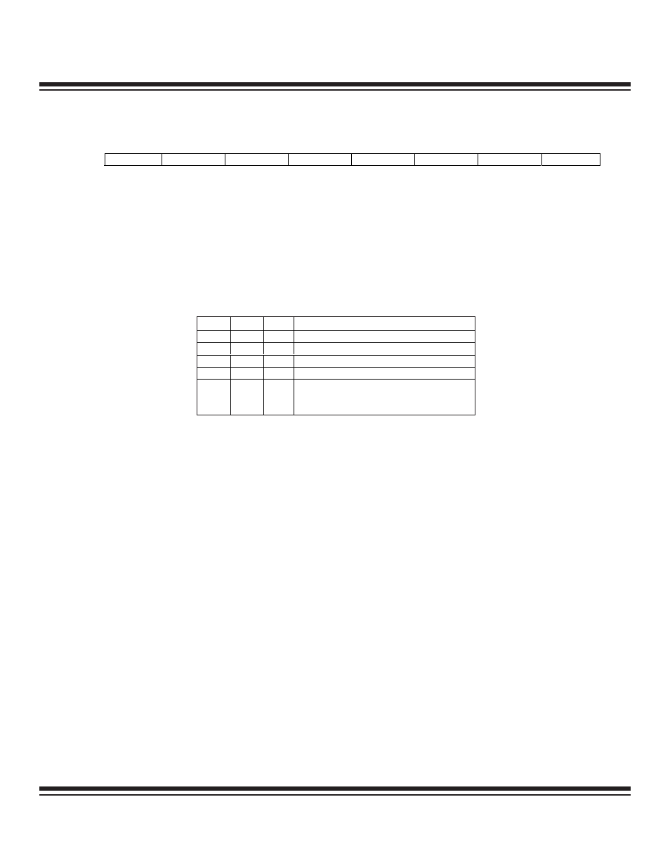
R = Unrestricted read, W = Unrestricted write, -n = Value after reset
Timer 2 Control (T2CON)
TF2
Bit 7
EXF2
Bit 6
Timer 2 Overflow Flag. This flag is set when Timer 2 overflows from FFFFh or the count equal to
the capture register in down count mode. It must be cleared by software. TF2 is only set if
RCLKand TCLK are both cleared to 0.
Timer 2 External Flag. A negative transition on the T2EX pin (P1.1) or timer 2 underflow/overflow
causes this flag to set based on the CP/RL2 (T2CON.0), EXEN2 (T2CON.3), and DCEN (T2MOD.0)
bits (see the following table). If set by a negative transition, this flag must be cleared to 0 by soft-
ware. Setting this bit in software or detection of a negative transition on the T2EX pin forces a timer
interrupt if enabled.
RCLK
Bit 5
TCLK
Bit 4
EXEN2
Bit 3
TR2
Bit 2
C/
T2
Bit 1
Receive Clock Flag. This bit determines the serial port 0 time base when receiving data in serial
modes 1 or 3. Setting this bit forces Timer 2 into baud-rate generation mode. The timer operates
from a divide-by-2 of the external clock.
0 = Timer 1 overflow is used to determine receiver baud rate for serial port 0.
1 = Timer 2 overflow is used to determine receiver baud rate for serial port 0.
Transmit Clock Flag. This bit determines the serial port 0 time base when transmitting data in ser-
ial modes 1 or 3. Setting this bit forces Timer 2 into baud rate generation mode. The timer operates
from a divide-by-2 of the external clock.
0 = Timer 1 overflow is used to determine transmitter baud rate for serial port 0.
1 = Timer 2 overflow is used to determine transmitter baud rate for serial port 0.
Timer 2 External Enable. This bit enables the capture/reload function on the T2EX pin if Timer 2
is not generating baud rates for the serial port.
0 = Timer 2 ignores all external events at T2EX.
1 = Timer 2 captures or reload a value if a negative transition is detected on the T2EX pin.
Timer 2 Run Control. This bit enables/disables the operation of Timer 2. Halting this timer preserves
the current count in TH2, TL2.
0 = Timer 2 is halted.
1 = Timer 2 is enabled.
Counter/Timer Select. This bit determines whether Timer 2 functions as a timer or counter.
Independent of this bit, Timer 2 runs at 2 clocks per tick when used in either baud-rate generator
or clock-output mode.
0 = Timer 2 function as a timer.
1 = Timer 2 counts negative transitions on the T2 pin (P1.0).
7
6
5
4
3
2
1
0
SFR C8h
TF2
EXF2
RCLK
TCLK
EXEN2
TR2
C/T2
CP/RL2
RW-0
RW-0
RW-0
RW-0
RW-0
RW-0
RW-0
RW-0
CP/
RL2 EXEN2 DCEN
RESULT
1
0
X
Negative transitions on P1.1 do not affect this bit.
1
1
X
Negative transitions on P1.1 set this bit.
0
0
0
Negative transitions on P1.1 do not affect this bit.
0
1
0
Negative transitions on P1.1 set this bit.
0
X
1
Bit toggles whenever Timer 2 underflows/overflows
and can be used as a 17th bit of resolution. In this
mode, EXF2 does not cause an interrupt.
Ultra-High-Speed Flash
Microcontroller User’s Guide
Maxim Integrated