Revision history – Maxim Integrated Ultra-High-Speed Flash Microcontroller User Manual
Page 169
Ultra-High-Speed Flash
Microcontroller User’s Guide
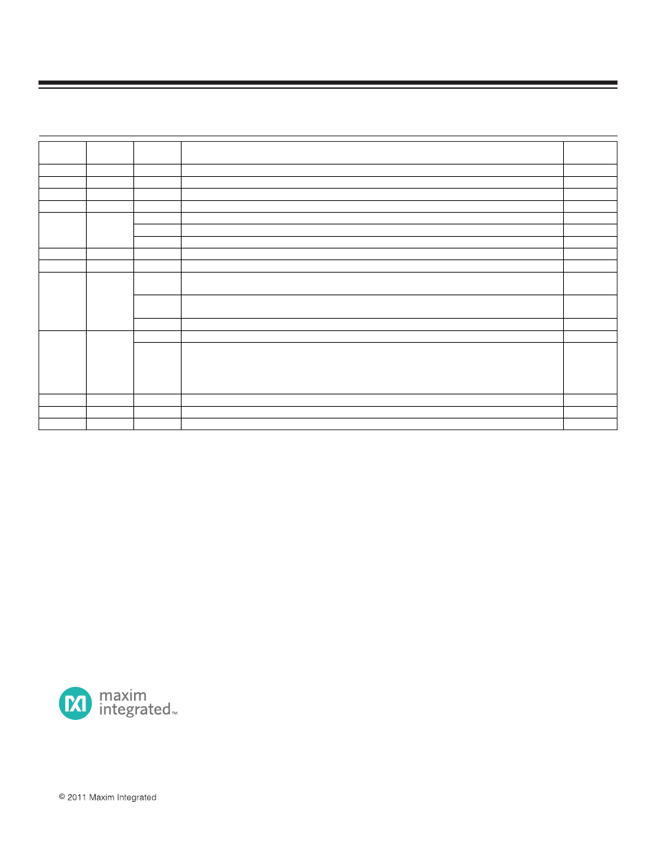
REVISION
NUMBER
REVISION
DATE
SECTION
NUMBER
DESCRIPTION
PAGES
CHANGED
0
1/01
—
Initial release.
—
1
10/02
—
Corrected some typos.
2
12/02
—
Changed title to reflect “flash” and removed “DS89C420” reference.
All
3
8/03
—
Made document universal to all Dallas ultra-high-speed microcontrollers.
All
4
Clarified that the CTM bit is cleared in stop mode.
14
5
Corrected cycle times for ADDC A, Rn instruction.
50
4
2/04
15
In the Command Summaries section, clarified that PMR SFR is not displayed in ROM loader.
133
5
8/04
4
Added FCNTL and FDATA to the Special-Function Register Locations table.
14, 15
6
12/04
15
Changed the ACK/NAK responses in the Command Summaries section.
136
15
In the Command Summaries section, clarified that the bootloader K command does not erase the option
control register, which controls the default state of the enable watchdog timer bit.
136
15
Removed information pertaining to the parallel programming mode and instead referred interested parties to
contact microcontroller technical support directly for more information.
138
7
10/05
4
Added Revision ID SFR.
14, 15, 26
12
Clarified the selection of the shift clock frequency for Mode 0 (first paragraph, last sentence).
116
8
3/07
14
In Instruction Set Details for the Data Transfer table section, changed "=" to " " for XCH A, Rn; XCH a, direct;
XCH A, @Ri; and XCHD A, @Ri; and changed ORLC, bit (72h) D7 from 1 to 0 in the Boolean Variable
Manipulation table section; changed the instruction code for JZ rel (60h) D7 from 1 to 0 and D6 and D5 from
0 to 1 and for JNZ rel (70h) D7 from 1 to 0 and D6, D5, and D4 from 0 to 1; changed the JNB bit, rel (30h) D5
from 0 to 1 and CJNE A, direct, rel (B5h) D6 from 0 to 1.
128, 129,
130
9
6/07
4
Corrected bit name headings for the RMS[2:0] table.
32
10
3/08
4
Corrected formatting errors.
23, 24
11
11/11
4
Corrected the Timer 1 and 0 bit descriptions for the CKMOD register (swapped 1 and 0 for respective timers)
4–21
REVISION HISTORY
Maxim Integrated 160 Rio Robles, San Jose, CA 95134 USA 1-408-601-1000
Maxim cannot assume responsibility for use of any circuitry other than circuitry entirely embodied in a Maxim product. No circuit patent licenses are implied.
Maxim reserves the right to change the circuitry and specifications without notice at any time. The parametric values (min and max limits) shown in the Electrical
Characteristics table are guaranteed. Other parametric values quoted in this data sheet are provided for guidance.
The Maxim logo and Maxim Integrated are trademarks of Maxim Integrated Products, Inc.