Program status flags, Special-function register lo, Program status flags -10 – Maxim Integrated Ultra-High-Speed Flash Microcontroller User Manual
Page 18: Special-function register locations -10, Special-function register locations, Table 4-1. instructions that affect flag settings, Bit description*: psw.7 c, Psw.6 ac, Psw.2 ov, Psw.0 p
4-10
Ultra-High-Speed Flash
Microcontroller User’s Guide
Program Status Flags
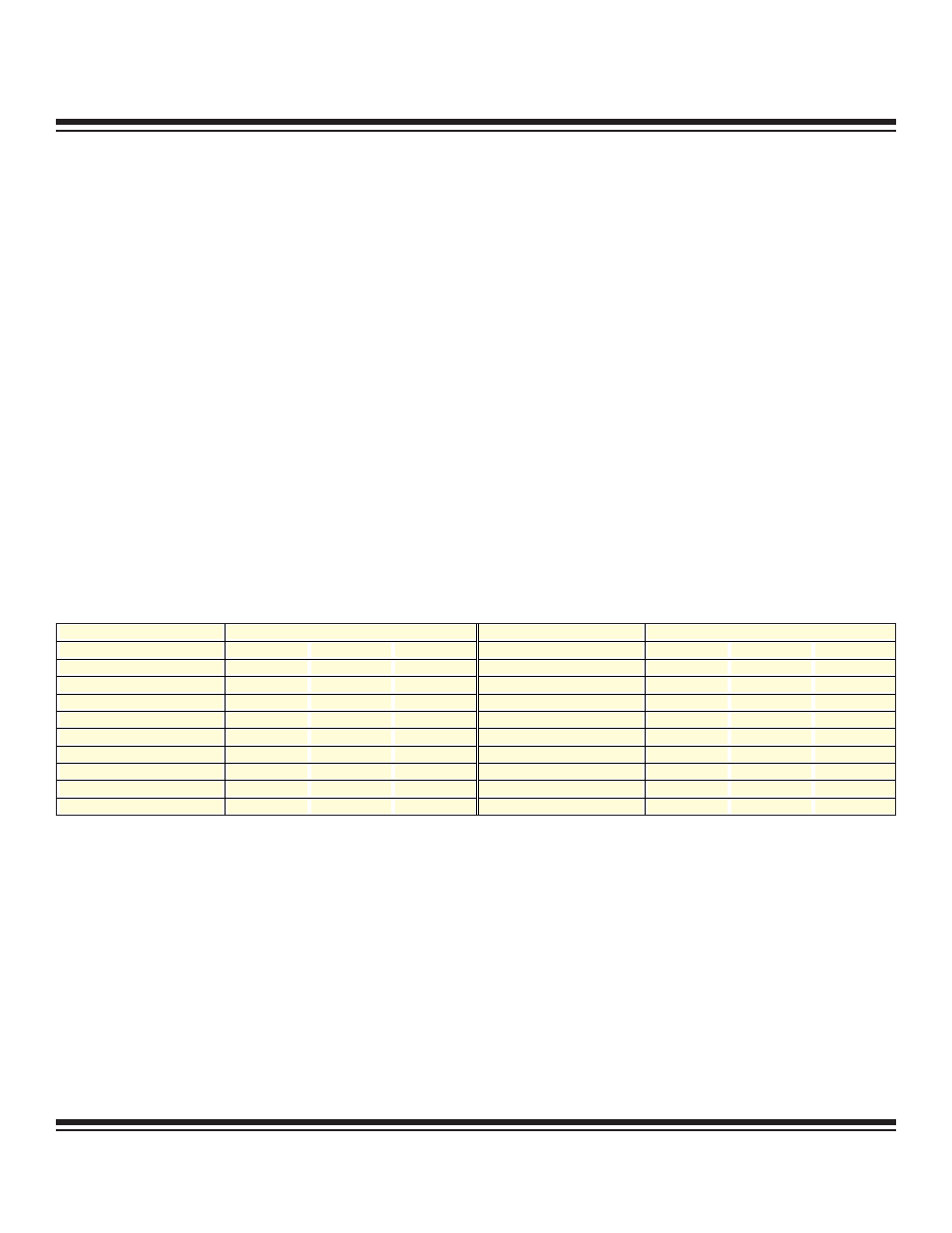
All program status flags are contained in the program status word at SFR location D0h. It contains flags that reflect the status of the CPU
and the result of selected operations. The flags are summarized below. The following table shows the instructions that affect each flag.
Bit Description*:
PSW.7
C
Carry
Set when the previous operation resulted in a carry (during addition) or a borrow (during subtraction). Otherwise
cleared.
PSW.6
AC
Auxiliary Carry
Set when the previous operation resulted in a carry (during addition) or a borrow (during subtraction) from the
high-order nibble. Otherwise cleared.
PSW.2 OV
Overflow
For addition, OV is set when a carry is generated into a high order bit (bit 6 or bit 7), but not a carry out of the
same high-order bit. For subtraction, OV is set if a borrow is needed into a high order bit (bit 6 or bit 7), but not
into the other high-order bit. For multiplication, OV is set when the product exceeds FFh. For division, OV is
always cleared.
PSW.0
P
Parity
Set to logic 1 to indicate an odd number of ones in the accumulator (odd parity). Cleared for an even number of
ones. This produces even parity.
*All of these bits are cleared to a logic 0 for all resets.
Special-Function Register Locations
The ultra-high-speed flash microcontroller, like the 8051, uses SFRs to control peripherals and modes. In many cases, an SFR controls
individual functions or report status on individual functions. The SFRs reside in register locations 80h–FFh and are reached using direct
addressing. SFRs that end in 0 or 8 are bit addressable.
All standard SFR locations from the original 8051 are duplicated, with several additions. Tables are provided to illustrate the locations
of the SFRs and the default reset conditions of all SFR bits. Detailed descriptions of each SFR follow.
INSTRUCTION
FLAGS
INSTRUCTION
FLAGS
C
OV
AC
C
OV
AC
ADD
X
X
X
CLR C
0
ADDC
X
X
X
CPL C
X
SUBB
X
X
X
ANL C, bit
X
MUL
0
X
ANL C, bit
X
DIV
0
X
ORL C, bit
X
DA
X
ORL C, bit
X
RRC
X
MOV C, bit
X
RLC
X
CJNE
X
SETB C
1
—
—
Note: X indicates the modification is according to the result of the instruction.
Table 4-1. Instructions that Affect Flag Settings
Maxim Integrated