Ring oscillator wake-up from, Speed reduction, Ring oscillator wake-up from stop -8 – Maxim Integrated Ultra-High-Speed Flash Microcontroller User Manual
Page 100: Speed reduction -8, Table 7-1. pin states in power-saving modes -8, Table 7-2. crystal vs. mips comparison -8, Ring oscillator wake-up from stop
7-8
Ultra-High-Speed Flash
Microcontroller User’s Guide
Ring Oscillator Wake-Up From Stop
A typical low-power application is to keep the processor in stop mode most of the time. Periodically, the system wakes up (using an
external interrupt), takes a reading of some condition, and then returns to sleep. The duration of full-power operation is as short as pos-
sible. One disadvantage to this method is that the clock must be restarted prior to performing a meaningful operation. This startup peri-
od is a waste of time and power since no work can be performed. The ultra-high-speed flash microcontroller provides an alternative.
If the ring select (RGSL) is enabled, the microcontroller can exit stop mode running from an internal ring oscillator. Upon receipt of an
interrupt, this oscillator can start instantaneously, allowing software execution to begin immediately while the oscillator is stabilizing.
Ring oscillator execution cannot be used to support accurate baud-rate generation or precise timer/counter operations. Once 65,536
clock cycles have been detected, the CPU automatically switches to the normal oscillator as its clock source. However, if the required
interrupt response is very short, the software can reenter stop mode before the crystal is even stable. In this case, stop mode can be
invoked and both oscillators are stopped.
Speed Reduction
The ultra-high-speed flash microcontroller is a fully CMOS 8051-compatible device. It can use significantly less power than other 8051
versions, because it is more efficient. As an average, software runs 10 times faster on the ultra-high-speed flash microcontroller than
on other 8051 derivatives. Thus, the same job can be accomplished by slowing down the crystal by a factor of 10. For example, an
existing 8051 design that runs at 12MHz can run at approximately 1.2MHz on the ultra-high-speed flash microcontroller. At this reduced
speed, the ultra-high-speed microcontroller has lower power consumption than an 8051, yet performs the same job.
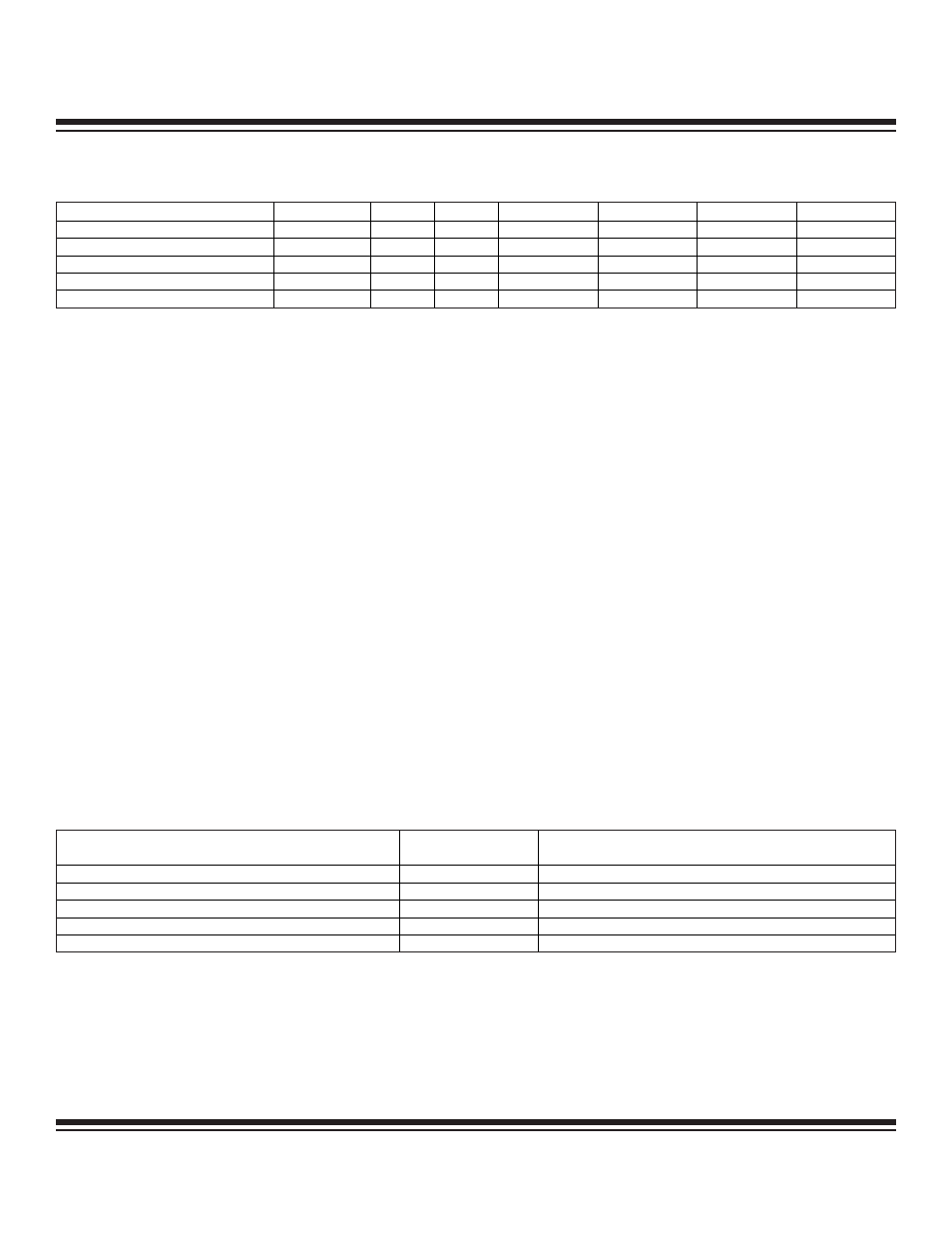
Using the 10X factor, Table 7-2 shows the approximate speed at which the ultra-high-speed flash microcontroller can accomplish the
same work as an 8051. The exact improvement varies depending on the actual instruction mix. Available crystal speeds must also be
considered. Refer to Section 14 for information on instruction timing.
Table 7-1. Pin States in Power-Saving Modes
Table 7-2. Crystal vs. MIPS Comparison
DEVICE EXECUTION
MODE
ALE
PSEN
P0
P1
P2
P3
Internal
Idle or stop
1
1
Port data
2
Port data
2
Port data
2
Port data
2
External nonpage
Idle
1
1
Latched
1
Port data
2
Latched
3
Port data
2
External page mode 1
Idle
1
1
Latched
1
Port data
2
Latched
5
Port data
2
External page mode 2
Idle
1
1
Latched
5
Port data
2
Latched
1
Port data
2
External (any)
Stop
1
1
Port data
2
Port data
2
Port data
4
Port data
2
1
Port exhibits opcode following instruction that sets the idle bit.
2
Port reflects data stored in corresponding port SFR. Port 0 functions as an open-drain output in this mode.
3
Port exhibits address MSB of opcode following instruction that sets the idle bit.
4
Port reflects data stored in corresponding port SFR. In this mode, the port uses weak pullups.
5
Port exhibits address LSB of opcode following instruction that sets the idle bit.
ORIGINAL 8051
CRYSTAL SPEED (MHz)
MIPS
ULTRA-HIGH-SPEED FLASH MICROCONTROLLER
CRYSTAL SPEED (MHz)
16
1.3
1.6
20
1.6
2.0
24
2.0
2.4
33
2.7
3.3
40
3.3
4.0
Maxim Integrated