Figure 11-9. watchdog timer -13 – Maxim Integrated Ultra-High-Speed Flash Microcontroller User Manual
Page 133
11-13
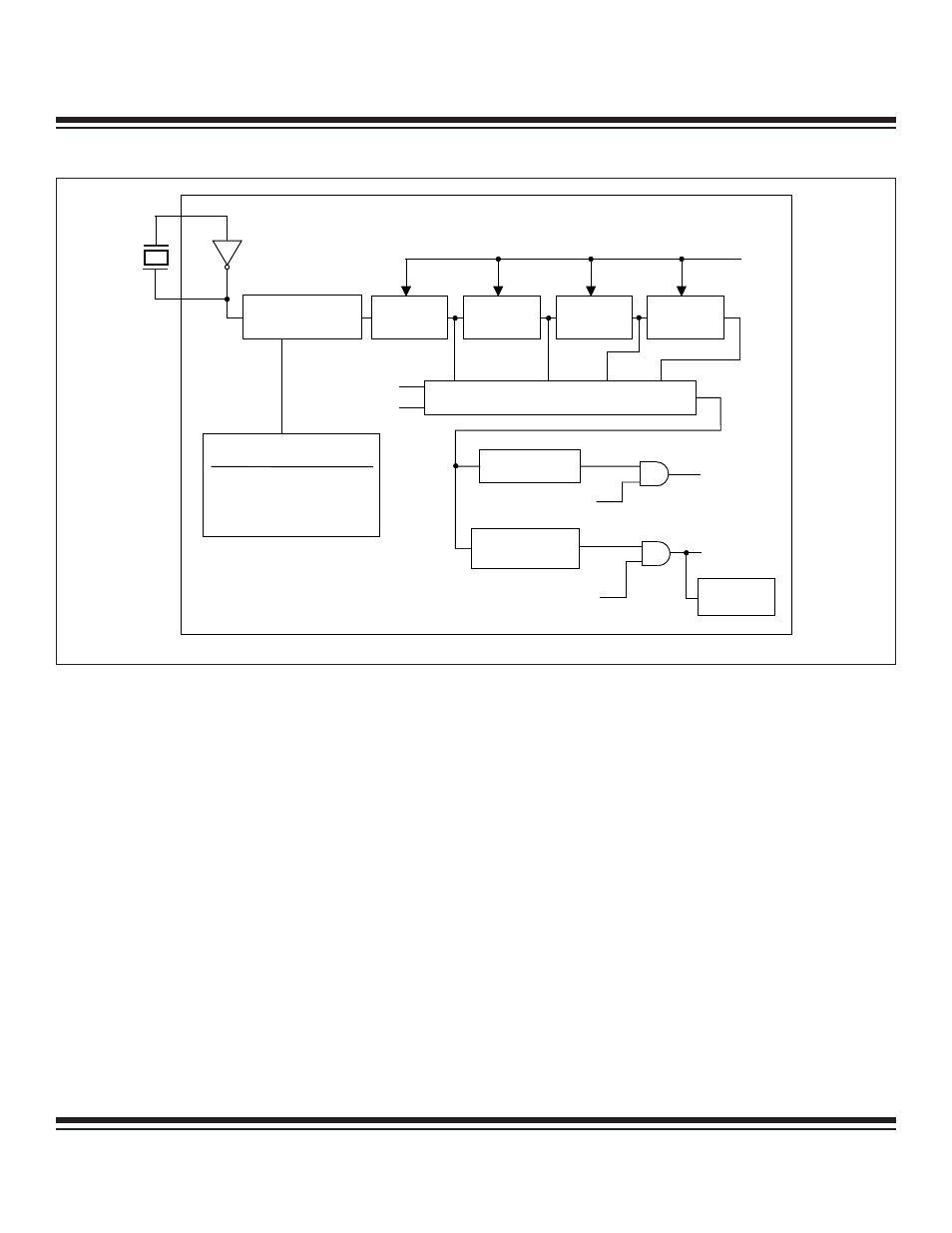
The watchdog interrupt is also available for applications that do not need a true watchdog reset, but a very long timer. The interrupt is
enabled using the enable watchdog timer interrupt (EWDI = EIE.4) bit. When the timeout occurs, the watchdog timer sets the WDIF bit
(WDCON.3), and an interrupt occurs if the global interrupt enable (EA = IE.7) is set. Note that WDIF is set 512 clocks before a poten-
tial watchdog reset. The watchdog interrupt flag indicates the source of the interrupt, and must be cleared by software.
Using the watchdog interrupt during software development can allow the user to select ideal watchdog reset locations. Code is first
developed without enabling the watchdog interrupt or reset functions. Once the program is complete, the watchdog interrupt function
is enabled to identify the required locations in code to set the RWT (WDCON.0) bit. Incrementally adding instructions to reset the watch-
dog timer prior to each address location (identified by the watchdog interrupt) allows the code to eventually run without receiving a
watchdog interrupt. At this point, the watchdog timer reset can be enabled without the potential of generating unwanted resets. At the
same time, the watchdog interrupt may also be disabled. Proper use of the watchdog interrupt with the watchdog reset allows inter-
rupt software to survey the system for errant conditions.
When using the watchdog timer as a system monitor, the watchdog reset function should be used. If the interrupt function were used,
the purpose of the watchdog would be defeated. For example, assume the system is executing errant code prior to the watchdog inter-
rupt. The interrupt would temporarily force the system back into control by vectoring the CPU to the interrupt service routine. Restarting
the watchdog and exiting by an RETI or RET would return the processor to the lost position prior to the interrupt. By using the watch-
dog reset function, the processor is restarted from the beginning of the program and, therefore, placed into a known state.
The watchdog timeout selection is made using bits WD1 (CKCON.7) and WD0 (CKCON.6). The watchdog has four timeout selections
based on the system clock frequency, as shown in the figure. Since the timeout is a function of the system clock, the actual timeout
interval is dependent on both the crystal frequency and the system clock mode. Shown in Table 11-4 is a summary of the selectable
watchdog timeout intervals for the various system clock modes and WD1:0 control bit settings. The watchdog reset, if enabled, is
always scheduled to occur 512 system clocks following the timeout. Watchdog-generated resets last for 13 oscillator cycles.
DIVIDE-BY-
2
17
DIVIDE-BY-
2
3
DIVIDE-BY-
2
3
DIVIDE-BY-
2
3
RWT (WDCON.0)
(RESET WATCHDOG)
WD1 (CKCON.7)
WD0 (CKCON.6)
TIMEOUT
XTAL1
XTAL2
SYSTEM CLOCK
MODE CONTROL
TIMEOUT
SELECTOR
WDIF
(WDCON.3)
EWDI (EIE.4)
(ENABLE WATCHDOG TIMER)
WATCHDOG
INTERRUPT
RESET
WTRF
(WDCON.2)
512 SYSCLK
DELAY
EWT (WDCON.1)
(ENABLE WATCHDOG TIMER)
2
17
2
20
2
23
2
26
SYSCLK OUTPUT
CLK MODE
SYSCLK
DIVIDE-BY-1 OSC / 1
2X
4X
OSC / 0.25
OSC / 0.5
PMM
OSC / 1024
Figure 11-9. Watchdog Timer
Ultra-High-Speed Flash
Microcontroller User’s Guide
Maxim Integrated