Mode 3, Timer 2 modes, Mode 3 -6 – Maxim Integrated Ultra-High-Speed Flash Microcontroller User Manual
Page 126: Timer 2 modes -6, Figure 11-2. timers/counters 0 and 1, mode 2 -6
11-6
Ultra-High-Speed Flash
Microcontroller User’s Guide
Mode 3
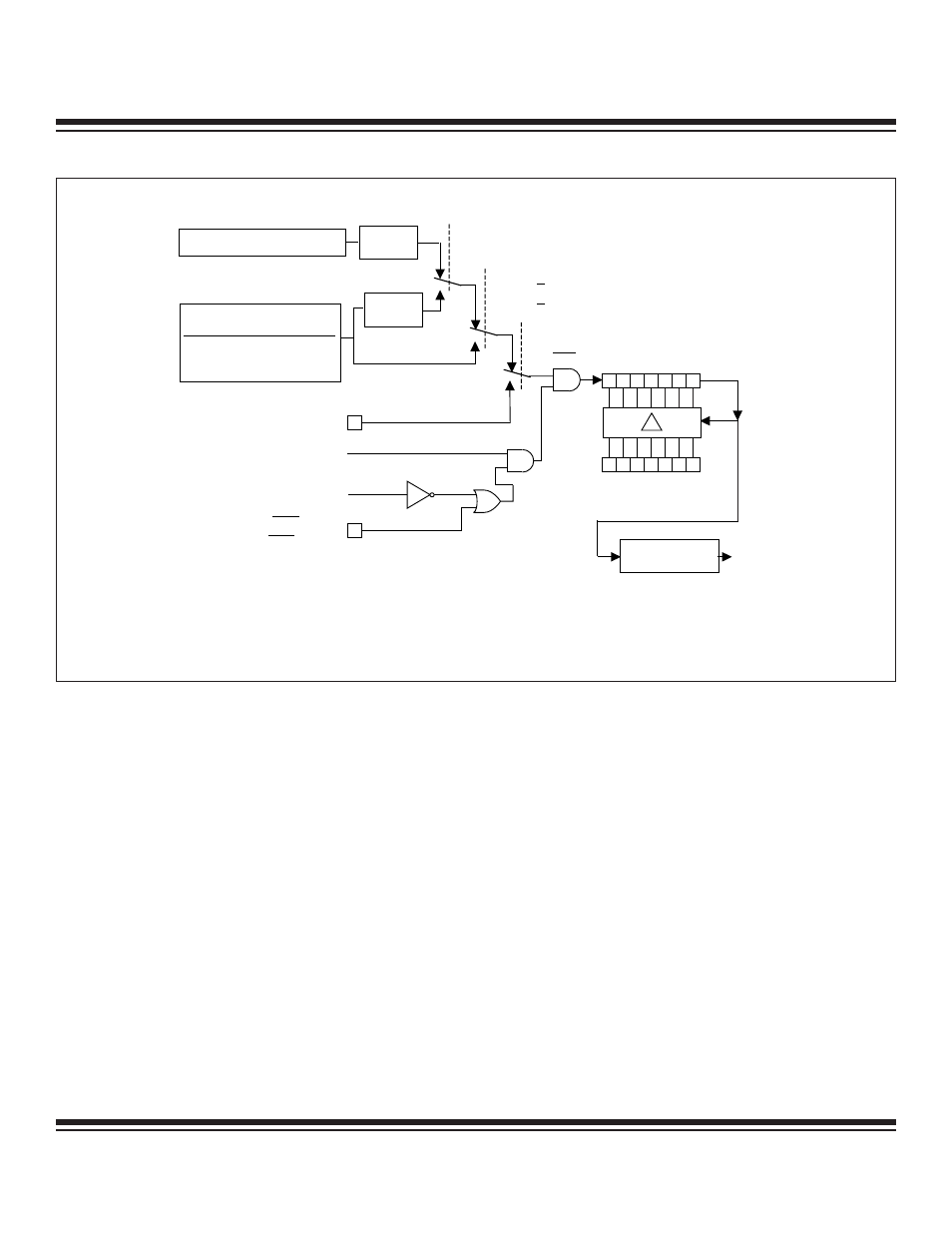
This mode provides an 8-bit timer/counter and a second 8-bit timer as indicated in Figure 11-3. In mode 3, TL0 is an 8-bit timer/counter
controlled by the normal timer 0 bits (TR0 = TCON.4 and TF0 = TCON.5). TL0 can be used to count clock cycles or 1 to 0 transitions
on pin T0, as determined by C/T(TMOD.2). As in the other modes, the GATE function can use INT0 to give external run control of the
timer to an outside signal.
TH0 becomes an independent 8-bit timer in mode 3; however, it can only count clock cycles as shown in Figure 11-2. In this mode,
some of timer 1’s control signals are used to manipulate TH0. That is, TR1 (TCON.6) and TF1 (TCON.7) become the relevant control
and flag bits associated with TH0.
In mode 3, timer 1 stops counting and holds its value. Thus, timer 1 has no practical application while in mode 3.
As mentioned, when timer 0 is in mode 3, it uses some of timer 1’s resources (i.e., TR1 and TF1). Timer 1 can still be used in modes
0, 1, and 2 in this situation, but its flexibility becomes somewhat limited. While it maintains its basic functionality, its inputs and outputs
are no longer available. Therefore, when timer 0 is in mode 3, timer 1 can only count clock cycles, and it does not have an interrupt or
flag. With these limitations, baud-rate generation is its most practical application, but other time-base functions may be achieved by
reading the registers.
Timer 2 Modes
Like timers 0 and 1, timer 2 is a full-function timer/counter; however, it has several additional capabilities that make it more useful. Timer
2 has independent control registers in T2CON and T2MOD, and is based on count registers TL2 and TH2. It does not offer the 13-bit
or dual 8-bit mode, but instead runs in the 16-bit mode at all times. Also note that while timers 0 and 1 have an 8-bit autoreload mode,
timer 2 provides a 16-bit autoreload mode. This mode uses the timer capture registers to hold the reload values. The modes available
on timer 2 are described in the following pages.
TF0 = TCON.5
(TF1 = TCON.7)
TIMER 1 FUNCTIONS
SHOWN IN PARENTHESES ()
INTERRUPT
TL0
(TL1)
0
7
0
7
TH0
(TH1)
RELOAD
DIVIDE-
BY-12
DIVIDE-
BY-4
0
1
0
0
EXTERNAL OSCILLATOR
1
T0M = CKCON.3
(T1M = CKCON.4)
T0MH = CKMOD.3
(T1MH = CKMOD.4)
T0 = P3.4
(T1 = P3.5)
TR0 = TCON.4
(TR1 = TCON.6)
GATE = TMOD.3
(GATE = TMOD.7)
INT0 = P3.2
( INT1 = P3.3)
1
C / T = TMOD.2
(C / T = TMOD.6)
NOTE: FOR POWER-MANAGEMENT MODE (DIVIDE-BY-1024) OPERATION, THE TIMER INPUT CLOCK TO THE TIMER IS
OSC / 1024 IF EITHER TXM = 1 OR TXMH = 1. OTHERWISE, THE TIMER INPUT IS OSC / 3072.
CLK
INPUT TO TIMER
CLK MODE
SYSCLK
DIVIDE-BY-1 OSC / 1
2X
4X
OSC / 0.25
OSC / 0.5
Figure 11-2. Timers/Counters 0 and 1, Mode 2
Maxim Integrated