Mode 1, Mode 2, Mode 1 -5 – Maxim Integrated Ultra-High-Speed Flash Microcontroller User Manual
Page 125: Mode 2 -5
11-5
Mode 1
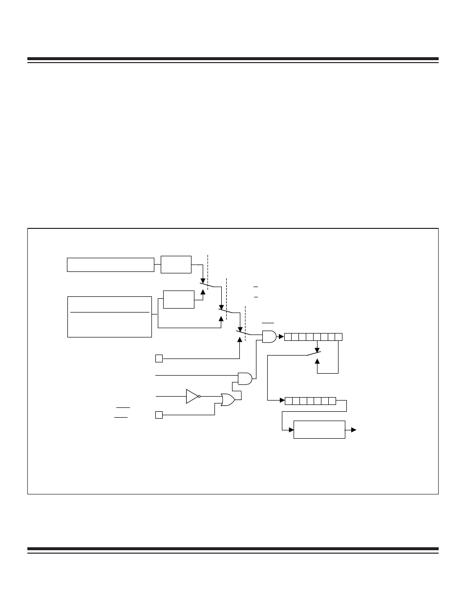
Mode 1 configures the timer for 16-bit operation as either a timer or counter. Figure 11-1 shows that setting the TMOD select bits M1,
M0 = 01b invoke this operating mode. For timer n, all of the TLn and THn registers are used. For example, if timer 1 is configured in
mode 1, then TL1 holds the LSB and TH1 holds the MSB. Rollover occurs when the timer reaches FFFFh. An interrupt also occurs if
enabled and the relevant TFn flag is set. Time-base selection, counter/timer selection, and the gate function operate as described in
mode 0.
Mode 2
This mode configures the timer as an 8-bit timer/counter with automatic reload of the start value. This configuration is shown in Figure
11-2, and is selected when bits M1and M0 of the TCON register are set to 1 and 0, respectively. When configured in mode 2, the timer
uses TLn to count and THn to store the reload value. Software must initialize both TLn and THn with the same starting value for the first
count to be correct. Once the TLn reaches FFh, it is automatically loaded with the value in THn. The THn value remains unchanged
unless modified by software. Mode 2 is commonly used to generate baud rates since it runs without continued software intervention.
As in modes 0 and 1, mode 2 allows counting of either clock cycles or pulses on pin Tn (C/T = 1) when counting is enabled by TRn
and the proper setting of GATE and INTn pins.
MODE 0
M1, M0 = TMOD.1,
TMOD.0
(M1, M0 = TMOD.5,
TMOD.4)
MODE 1
INPUT TO TIMER
CLK MODE
SYSCLK
DIVIDE-BY-1 OSC / 1
2X
4X
OSC / 0.25
OSC / 0.5
DIVIDE-
BY-12
DIVIDE-
BY-4
T0 = P3.4
(T1 = P3.5)
TR0 = TCON.4
(TR1 = TCON.6)
GATE = TMOD.3
(GATE = TMOD.7)
INT0 = P3.2
( INT1 = P3.3)
TF0 = TCON.5
(TF1 = TCON.7)
TIMER 1 FUNCTIONS
SHOWN IN PARENTHESES ()
INTERRUPT
TL0
(TL1)
0
4
7
00
01
0
7
TH0
(TH1)
CLK
0
1
0
1
T0M = CKCON.3
(T1M = CKCON.4)
C / T = TMOD.2
(C / T = TMOD.6)
0
EXTERNAL OSCILLATOR
T0MH = CKMOD.3
(T1MH = CKMOD.4)
1
NOTE: FOR POWER-MANAGEMENT MODE (DIVIDE-BY-1024) OPERATION, THE TIMER INPUT CLOCK TO THE TIMER IS
OSC / 1024 IF EITHER TXM = 1 OR TXMH = 1. OTHERWISE, THE TIMER INPUT IS OSC / 3072.
Figure 11-1. Timers/Counters 0 and 1, Modes 0 and 1
Ultra-High-Speed Flash
Microcontroller User’s Guide
Maxim Integrated