Up/down-count autoreload tim, Baud-rate generator, Up/down-count autoreload timer/counter -9 – Maxim Integrated Ultra-High-Speed Flash Microcontroller User Manual
Page 129: Baud-rate generator -9, Up/down-count autoreload timer/counter
11-9
When in autoreload mode, timer 2 can also be forced to reload with the T2EX (P1.1) pin. A 1 to 0 transition forces a reload if enabled by
the EXEN2 (T2CON.3) bit. If EXEN2 is set to a logic 1, then a 1 to 0 transition on T2EX causes a reload. Otherwise, the T2EX pin is ignored.
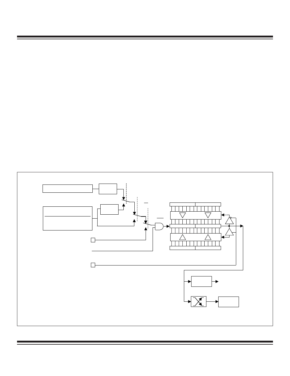
Up/Down-Count Autoreload Timer/Counter
The up/down autoreload counter option is selected by the DCEN (T2MOD.0) bit, and is illustrated in Figure 11-6. When DCEN
(T2MOD.0) is set to a logic 1, timer 2 counts up or down as controlled by the state of pin T2EX (P1.1). T2EX causes upward counting
when a logic 1 is applied and down counting when a logic 0 is applied. When DCEN = 0, timer 2 only counts up.
When an upward counting overflow occurs, the value in RCAP2L and RCAP2H loads into TL2 and TH2. In the down-count direction,
an underflow occurs when TL2 and TH2 match the values in RCAP2L and RCAP2H, respectively. When an underflow occurs, FFFFh
is loaded into TL2 and TH2 and counting continues.
Note that, in this mode, the overflow/underflow output of the timer is provided to an edge-detection circuit as well as to the TF2 bit
(T2CON.7). This edge-detection circuit toggles the EXF2 bit (T2CON.6) on every overflow or underflow. Therefore, the EXF2 bit behaves
as a 17th bit of the counter, and may be used as such.
Baud-Rate Generator
Timer 2 can be used to generate baud rates for serial port 0 in serial mode 1 or 3. Baud-rate generator mode is invoked by setting
either the RCLK or TCLK bit in the T2CON register to a logic 1, as illustrated in Figure 11-7. In this mode, the timer continues to func-
tion in autoreload mode, but instead of setting the interrupt flag TF2 (T2CON.7) and potentially causing an interrupt, the overflow gen-
erates the shift clock for the serial port function. As in normal autoreload mode, an overflow causes RCAP2L and RCAP2H to be trans-
ferred into T2L and T2H, respectively. Note that, when RCLK or TCLK is set to 1, timer 2 is forced into 16-bit autoreload mode, regard-
less of the CP/RL2 bit.
T2 = P1.0
TR2 = T2CON.2
1
T2M = CKCON.5
RCAP2L
R AP2H
0FFH
0FFH
0
7 8
15
TL2
TH2
(DOWN-COUNTING RELOAD VALUE)
0
7 8
15
T2EX = P1.1
(UP-COUNTING RELOAD VALUE)
TF2 =
T2CON.7
TIMER 2
INTERRUPT
EXF2 =
T2CON.6
COUNT DIRECTION
(1 = UP, 0 = DOWN)
C /
T2
= T2CON.1
CLK
0
DIVIDE-
BY-12
DIVIDE-
BY-4
0
1
0
EXTERNAL OSCILLATOR
1
T2MH = CKMOD.5
NOTE: FOR POWER-MANAGEMENT MODE (DIVIDE-BY-1024) OPERATION, THE TIMER INPUT CLOCK TO THE TIMER IS
OSC / 1024 IF EITHER TXM = 1 OR TXMH = 1. OTHERWISE, THE TIMER INPUT IS OSC / 3072.
SYSCLK
OSC / 1
OSC / 0.25
INPUT TO TIMER
CLK MODE
DIVIDE-BY-1
2X
4X
OSC / 0.5
Figure 11-6. Timer/Counter 2 Autoreload Mode (DCEN = 1)
Ultra-High-Speed Flash
Microcontroller User’s Guide
Maxim Integrated