Time-base selection, Time-base selection -11 – Maxim Integrated Ultra-High-Speed Flash Microcontroller User Manual
Page 131
11-11
Time-Base Selection
The ultra-high-speed microcontroller allows the user to select the time base for each timer independently. In the standard 8051, the
timers count the oscillator divided by 12, which is the standard 8051 machine cycle timing. Following a reset, the timers default to an
oscillator divided-by-12 input clock to remain drop-in compatible with the original 8051. The ultra-high-speed microcontroller timers
can additionally be configured to use the system clock or the system clock divided by 4 for the input clock. These selections, while not
affecting the CPU timing, allow for higher precision timing and faster baud rates. As an example, a user might select both the baud-
rate generator timer and another timer to run at 12 oscillator clocks per timer tick with the third timer running at four system clocks per
tick. This allows one timer to measure higher speed events or to gain better resolution.
The input clock selection is independent for each timer and the default is 12 oscillator clocks per timer tick. The control bits for the
time-base selection (TxM, TxMH) are located in the clock control register (CKCON;8Eh) and the clock-mode register (CKMOD;96h).
The TxM and TxMH bits for each of the timers enable input clock selections of the system clock divided by 4 and the system clock
divided by 1, respectively. When TxMH is set to a logic 1, the associated TxM bit for that timer is ignored. Note that, when operating
in the default system clock mode, the system clock is the same frequency as the oscillator clock. System clock mode selection is con-
trolled by the CD1, CD0 bits of the PMR register. See the PMR register description and the CPU timing section for more information on
how to modify the system clock. As described earlier, timer 2 does, however, automatically switch to two oscillator clocks per tick when
configured for baud-rate generation or clock-output mode. When the time base is derived from an external source (i.e., the T0, T1, or
T2 pins), the timer operates at the frequency of the external source and is not affected by the setting of the TxM or TxMH bits. The only
limitation is that the external source frequency can be no faster than one-fourth of the main system clock frequency. Use of power man-
agement-mode changes the input clock to the timers in a way that does not exactly follow any of the guidelines set forth to this point.
Tables 11-2 and 11-3 show the resulting timer input clock for the various system clock modes and timer control bit setting. Table 11-2
pertains only to timer 2 in the baud-rate generation or clock-output mode.
Ultra-High-Speed Flash
Microcontroller User’s Guide
EXF2 =
T2CON.6
DIVIDE-
BY-2
T2EX = P1.1
EXEN2 = T2CON.3
RCAP2L
RCAP2H
0
15
TL2
TH2
0
7 8
15
T2 = P1.0
7 8
C/T2 = T2CON.1 = 0
TR2 =
T2CON.2
T2OE = T2MOD.1
TIMER 2
INTERRUPT
OSC INPUT TO TIMER
CLK MODE
TIMER INPUT
DIVIDE-BY-1 OSC / 2
2X
OSC / 2
4X
OSC / 2
PMM ( / 1024) OSC / 2048
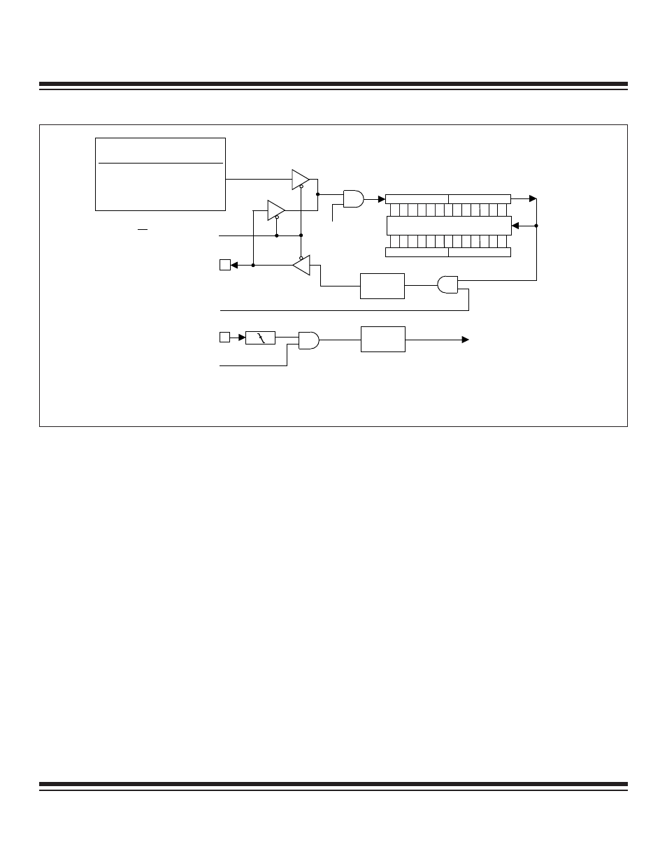
T2 FREQUENCY OUT = TIMER CLOCK INPUT / (2 x (65536—RCAP2H, RCAP2L))
Figure 11-8. Timer/Counter 2 Clock Out Mode Time–Base Selection
Maxim Integrated