Timer output clock generator, Timer output clock generator -10 – Maxim Integrated Ultra-High-Speed Flash Microcontroller User Manual
Page 130
11-10
Ultra-High-Speed Flash
Microcontroller User’s Guide
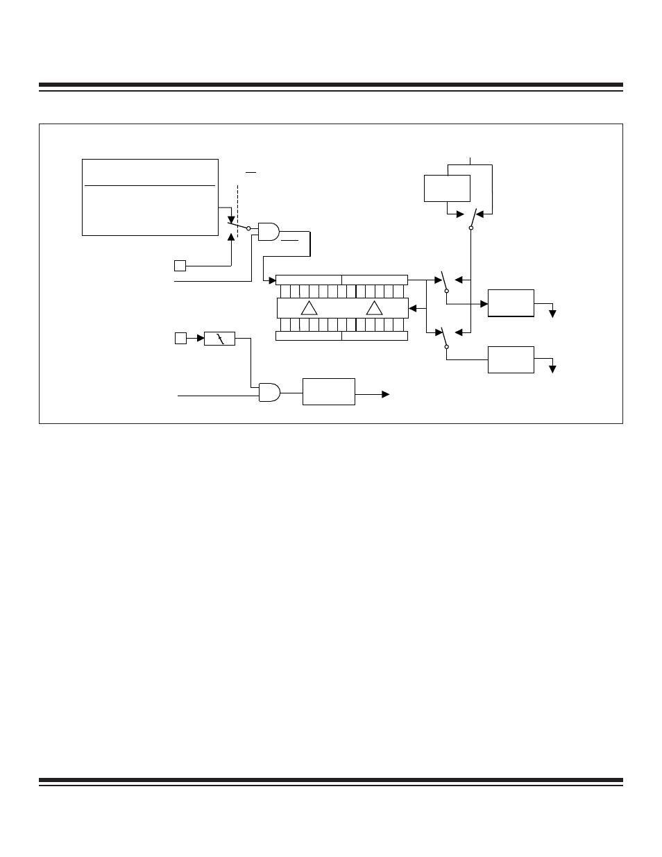
As explained above, the timer itself cannot set the TF2 interrupt flag and, therefore, cannot generate an interrupt. However, if EXEN2
(T2CON.3) is set to 1, a 1 to 0 transition on the T2EX (P1.1) pin causes the EXF2 (T2CON.6) interrupt flag to be set. If enabled, this
causes a timer 2 interrupt to occur. Therefore, in this mode, the T2EX pin may be used as an additional external interrupt, if desired.
Another feature of the baud-rate generator mode is that the crystal-derived time base for the timer is the crystal frequency divided by
2. No other crystal-divider selection is possible unless operating in power-management mode. If a different time base is desired, bit
C/T2 (T2CON.1) may be set to a 1, sourcing the time base from an external clock source supplied by the user on pin T2 (P1.0). The
RCAP registers may be read, but not modified, while TR2 = 1. Stop the timer (TR2 = 0) to modify these registers.
Timer Output Clock Generator
Timer 2 can also be configured to drive a clock output on port pin P1.0 (T2), as shown in Figure 11-8. To configure timer 2 for this mode,
it must first be set to 16-bit autoreload timer mode (CP/RL2 = 0, C/T2 = 0). Next, the T2OE (T2MOD.1) bit must be set to a logic 1. TR2
(T2CON.2) must also be set to a logic 1 to enable the timer.
This mode produces a 50% duty cycle square-wave output. The frequency of the square wave is given by the formula in Figure 11-7.
Each timer overflow causes an edge transition on the pin, i.e., the state of the pin toggles.
Note that this mode has two somewhat unique features in common with the baud-rate generation mode. First, the time base is the crys-
tal frequency divided by 2, and other than power-management mode operation, no other divider selection is possible. Second, the
timer itself does not generate an interrupt, but, if needed, an additional external interrupt may be caused using T2EX as described
above. Because of the two modes’ similarities, the timer can be used to generate both an external clock and a baud-rate clock simul-
taneously. Once the clock-out mode is established, either TCLK or RCLK is set to 1, and the RCAP2 registers are loaded, the timer
provides a clock to both functions.
OSC INPUT TO TIMER
CLK MODE
TIMER INPUT
DIVIDE BY 1 OSC / 2
2X
OSC / 2
4X
OSC / 2
PMM ( / 1024) OSC / 2048
DIVIDE-
BY-2
T2 = P1.0
TR2 = T2CON.2
EXEN2 = T2CON.3
EXF2 =
T2CON.6
TIMER 2
INTERRUPT
0
1
TL2
0
7
TH2
8
15
RCLK =
T2CON.5
0
7 8
15
RCAP2L
RCAP2H
T2EX = P1.1
Tx
CLOCK
DIVIDE-
BY-16
Rx
CLOCK
DIVIDE-
BY-1 6
SMOD_0 =
PCON.7
TCLK =
T2CON.4
1
0
1
0
0
1
TIMER 1
OVERFLOW
C / T2 = T2CON.1
CLK
Figure 11-7. Timer/Counter 2 Baud-Rate Generator Mode
Maxim Integrated