Bit timer/counter with op, Bit autoreload timer/counter, Bit timer/counter with optional capture -7 – Maxim Integrated Ultra-High-Speed Flash Microcontroller User Manual
Page 127: Bit autoreload timer/counter -7, Figure 11-3. timer/counter 0, mode 3 -7, Bit timer/counter with optional capture
11-7
16-Bit Timer/Counter with Optional Capture
In this mode, timer 2 performs a simple timer or counter function where it behaves similarly to mode 1 of timers 0 and 1, but uses 16
instead of 8 bits. This mode, along with the optional capture mode described later, is illustrated in Figure 11-4. The 16-bit count values
are found in TL2 and TH2 special function registers (addresses 0CCh and 0CDh, respectively). The selection of whether a timer or
counter function is performed is made using bit C/T2 (T2CON.1). When C/T2 is set to a logic 1, timer 2 behaves as a counter where it
counts 1 to 0 transitions at the T2 (P1.0) pin. When C/T2 is set to a logic 0, timer 2 functions as a timer where it counts clock cycles.
Timing or counting is enabled by setting bit TR2 (T2CON.2) to 1, and disabled by setting it to zero. When the counter rolls over from
FFFFh to 0000h, the TF2 flag (T2CON.7) is set and causes an interrupt if timer 2’s interrupt is enabled.
A diagram of timer 2’s capture mode is shown in Figure 11-4. In this mode, the timer performs basically the same 16-bit timer/counter
function described above. However, a 1 to 0 transition on T2EX (pin P1.1) causes the value in timer 2 to be transferred into the cap-
ture registers if enabled by EXEN2 (T2CON.3). The capture registers, RCAP2L and RCAP2H, correspond to TL2 and TH2, respective-
ly. The capture function is enabled by the CP/RL2 (T2CON.0) bit. When this bit is set to logic 1, the timer is in the capture mode just
described. When set to logic 0, the timer is in autoreload mode described later.
16-Bit Autoreload Timer/Counter
This mode is illustrated in Figure 11-5. When timer 2 reaches an overflow state, i.e., rolls over from FFFFh to 0000, it sets the TF2 flag.
This flag can generate an interrupt if enabled. In addition, the timer restores its starting value and begins timing (or counting) again.
The starting value is preloaded by software into capture registers RCAP2L and RCAP2H. These registers cannot be used for capture
functions while also performing autoreload, so these modes are mutually exclusive. Autoreload is invoked by the CP/RL2 (T2CON.0)
bit. When set to a logic 0, the timer is in autoreload mode. When CP/RL2 is set to a logic 1, the timer is in capture mode described
above. If the C/T2 bit (T2CON.1) is a logic 0, the timer’s input clock is selectable as a function of the external oscillator or the system
clock. Otherwise, pulses on pin T2 (P1.0) are counted when C/T2
=
1. As in other modes, counting or timing is enabled or disabled
with TR2 (T2CON.2).
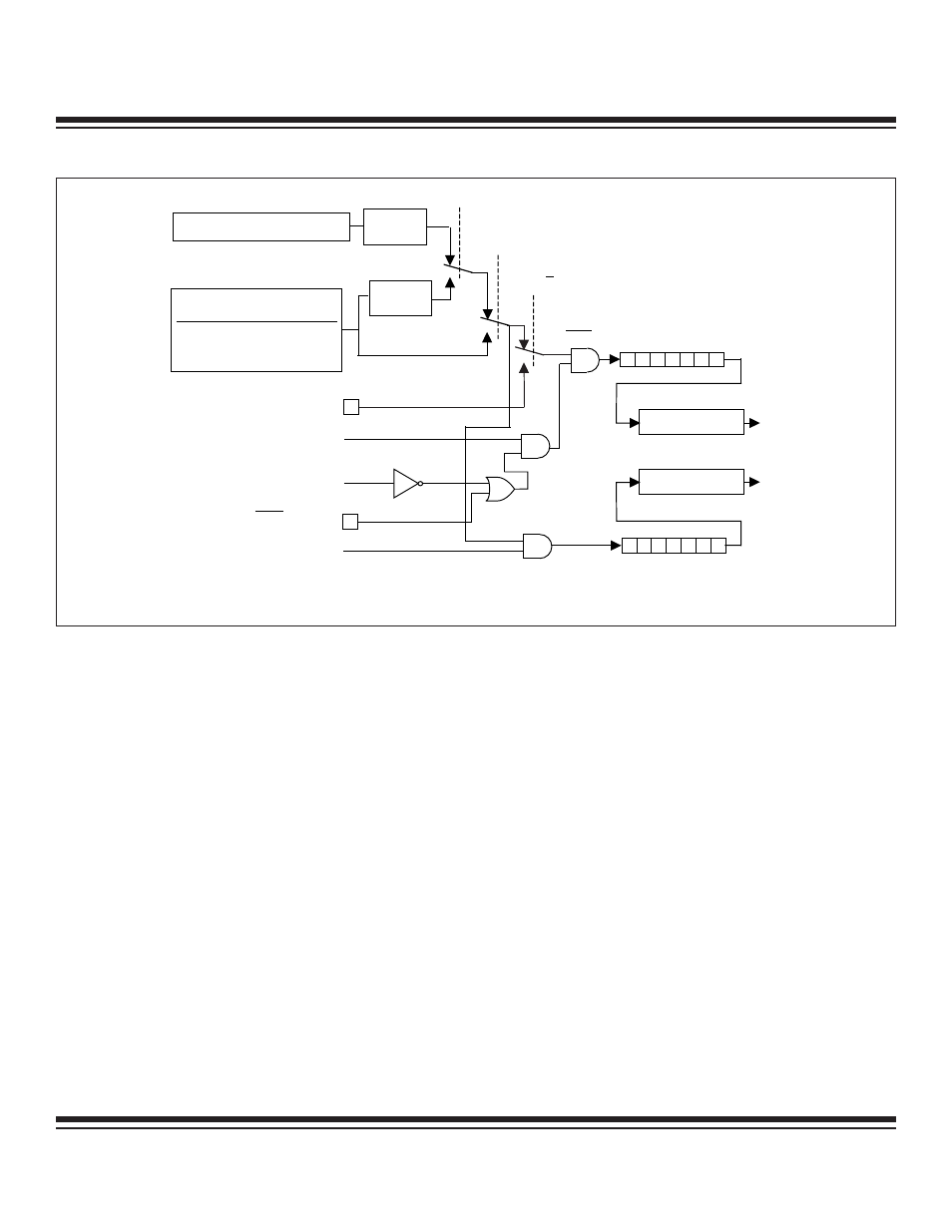
T0 = P3.4
TR0 = TCON.4
GATE = TMOD.3
TL0
0
7
0
7
TH0
0
1
TR1 = TCON.6
TF0 = TCON.5
INTERRUPT
TF1 = TCON.7
C / T = TMOD.2
INT0 = P3.2
CLK
INTERRUPT
DIVIDE-
BY-12
DIVIDE-
BY-4
0
1
0
EXTERNAL OSCILLATOR
1
T0M = CKCON.3
T0MH = CKMOD.3
INPUT TO TIMER
CLK MODE
SYSCLK
DIVIDE-BY-1 OSC / 1
2X
4X
OSC / 0.25
OSC / 0.5
NOTE: FOR POWER-MANAGEMENT MODE (DIVIDE-BY-1024) OPERATION, THE TIMER INPUT CLOCK TO THE TIMER IS
OSC / 1024 IF EITHER TXM = 1 OR TXMH = 1. OTHERWISE, THE TIMER INPUT IS OSC / 3072.
Figure 11-3. Timer/Counter 0, Mode 3
Ultra-High-Speed Flash
Microcontroller User’s Guide
Maxim Integrated