Precision voltage monitor, Early-warning power-fail int, Precision voltage monitor -4 – Maxim Integrated Ultra-High-Speed Flash Microcontroller User Manual
Page 96: Early-warning power-fail interrupt -4, Figure 7-1. power cycle operaton -4, Early-warning power-fail interrupt
7-4
Ultra-High-Speed Flash
Microcontroller User’s Guide
EXIF.2
RGMD: Ring oscillator mode. Hardware sets this status bit to a 1 when the clock source is the ring oscillator.
Hardware sets this status bit to a 0 when the crystal is the clock source. Refer to RGSL for operation of the ring oscil-
lator.
EXIF.1
RGSL: Ring oscillator select. When set to a 1 by software, the microcontroller uses a ring oscillator to come out of
stop mode without waiting for crystal startup. This allows an instantaneous startup when coming out of stop mode. It
is useful if software needs to perform a short task, and then return to stop. It is also useful if software must respond
quickly to an external event. After the crystal has performed 65,536 cycles, hardware switches to the crystal as its
clocksource. The RGMD status bit reports on this changeover. When RGSL is set to a 0, the microcontroller delays
software execution until after the 65,536 clock crystal startup time. RGSL is only cleared by a power-on reset and is
not altered by other forms of reset.
Precision Voltage Monitor
A precision bandgap reference and other analog circuits monitor the state of the power supply during power-up and power-down tran-
sitions. This obviates the need for external circuits to perform these functions that other microcontroller systems would require. The
bandgap reference provides a precise voltage to compare with V
CC
. When V
CC
begins to drop, the power monitor compares it to its
reference. This enables the analog circuits to detect when V
CC
passes through predetermined thresholds, V
PFW
and V
RST
. These are
specified in the product data sheet.
Early-Warning Power-Fail Interrupt
The precision voltage reference has the ability to generate a power-fail interrupt and/or reset in response to a low-supply voltage. When
V
CC
reaches the V
PFW
threshold, the microcontroller can generate a power-fail interrupt. This early warning of supply voltage failure
allows the system time to save critical parameters in nonvolatile memory and put external functions in a safe state.
The power-fail interrupt is optional and is enabled using the enable power-fail warning interrupt (EPFI) bit at WDCON.5. If enabled, V
CC
dropping below V
PFW
causes the device to vector to address 33h. The power-fail interrupt status bit, PFI (WDCON.4), is set anytime
VCC transitions below V
PFW
. This flag is not cleared when V
CC
is above V
PFW
, and software should clear it immediately after reading
it. As long as the condition exists, PFI is immediately set again by hardware.
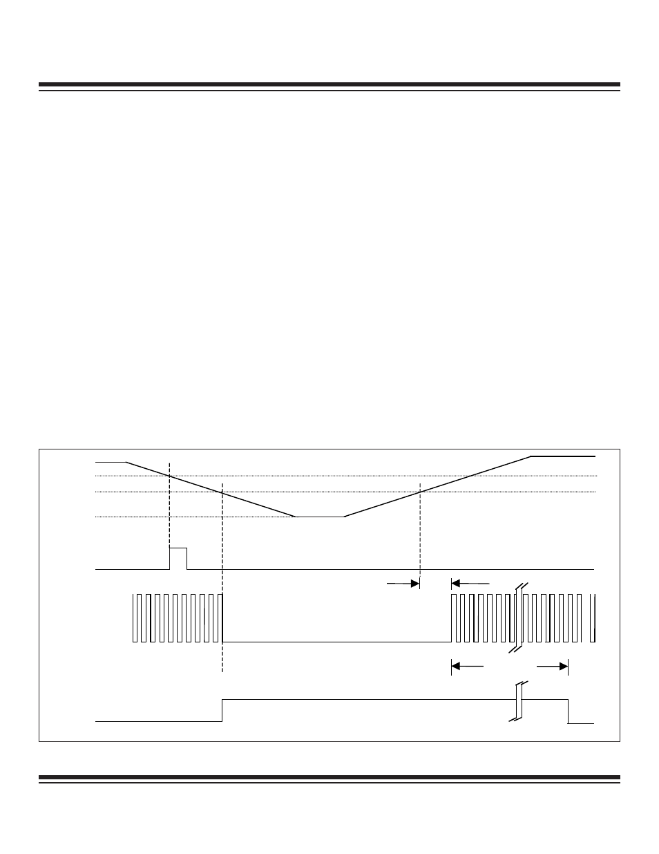
V
CC
V
PFW
V
RST
V
SS
INTERRUPT
SERVICE ROUTINE
INTERNAL RESET
XTAL1
t
POR
t
CSU
Figure 7-1. Power Cycle Operaton
Maxim Integrated