Maxim Integrated Ultra-High-Speed Flash Microcontroller User Manual
Page 58
5-11
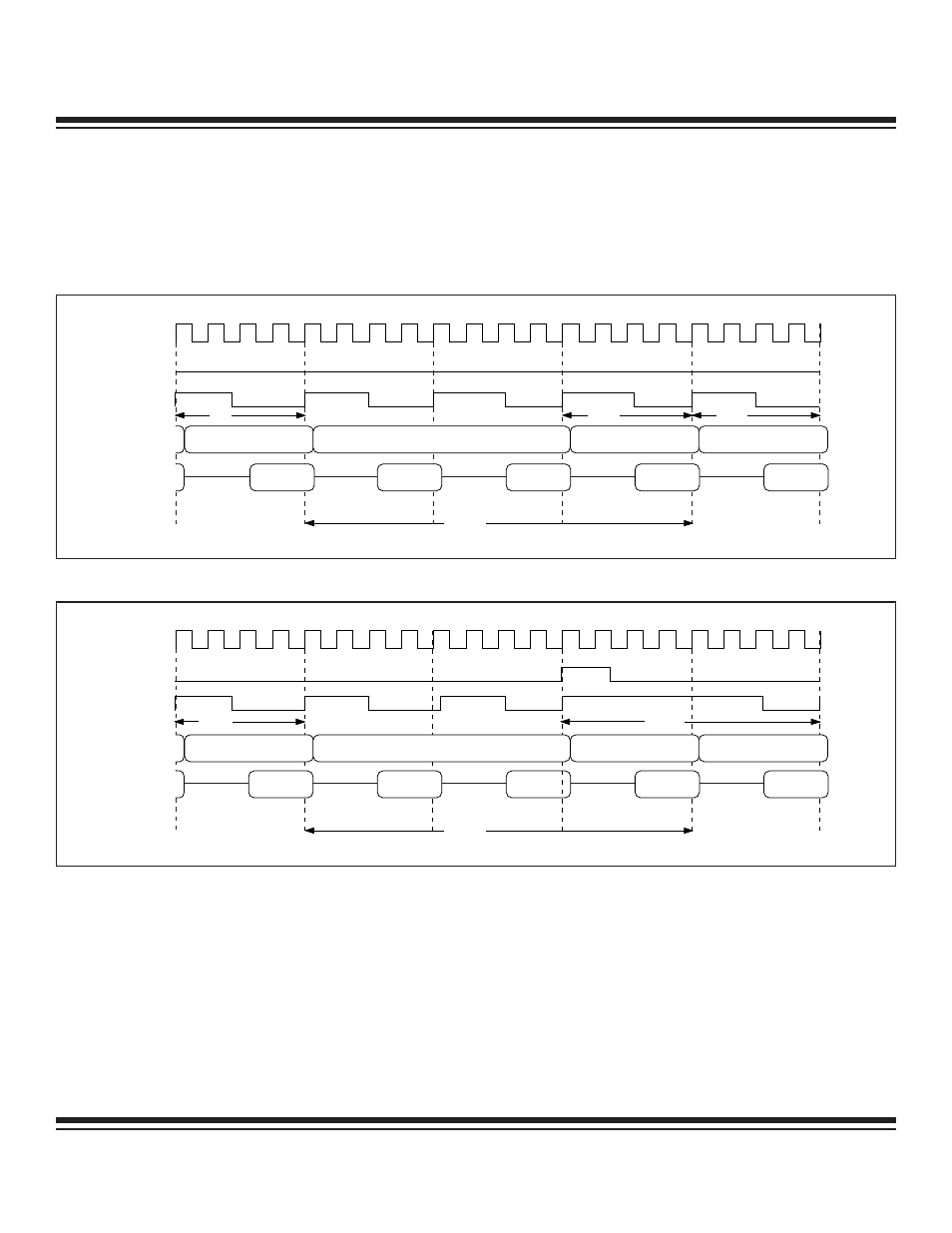
Page Mode 1 External Timing—Pages 1:0 = 10b (Four Cycles) (continued)
Figure 5-13 and Figure 5-14 demonstrate the execution of the RET (1-byte, three cycles) instruction. In Figure 5-13, the return address
resides on the same 256-byte page as that of the executed RET instruction. Two stall cycles are inserted followed by a page-hit mem-
ory cycle. In Figure 5-14, the return address is on a different 256-byte page from where the RET instruction was executed. In this case,
two stall cycles are inserted, followed by a page-miss memory cycle.
STALL
STALL
SYSCLK
ALE
PSEN
PORT 2
PORT 0
ACALL
22
MISS
HIT
LSB ADDRESS
LSB ADDRESS
MSB ADDRESS
LSB ADDRESS
Figure 5-14. Four-Cycle Page Mode 1: RET – (Page Miss)
SYSCLK
ALE
PSEN
PORT 2
PORT 0
22
HIT
HIT
HIT
STALL
STALL
RET
LSB ADDRESS
LSB ADDRESS
LSB ADDRESS
LSB ADDRESS
Figure 5-13. Four-Cycle Page Mode 1: RET
Ultra-High-Speed Flash
Microcontroller User’s Guide
Maxim Integrated
- DS80C390 (58 pages)
- DS5001FP (26 pages)
- MAX1416 (14 pages)
- MAX5865 (18 pages)
- DS33Z41 (167 pages)
- MAX1202 (7 pages)
- USBTO232 (31 pages)
- HFAN-09.5.0: Pattern Creator/Converter Software (8 pages)
- MAX-IDE MAXQ Microcontrollers (11 pages)
- MAX6876 Power-Supply Tracker/Sequencer (6 pages)
- MAX6877 Power-Supply Tracker/Sequencer (3 pages)
- 78Q8430 ARM9(920T) Linux Driver Diagnostic Guide (19 pages)
- 78Q8430 Software Driver (54 pages)
- 78Q8430 ST 5100/OS-20 with NexGen TCP/IP Stack (28 pages)
- 6612_OMU_S2_URT_V1_13 (56 pages)
- 6612_OMU_S2+2_URT_V1_14 (58 pages)
- 71M6511 Power Meter IC Family Software (137 pages)
- 71M65xx ADM51 ICE Safety Notice (2 pages)
- 71M6511 2-Layer Demo Board (2 pages)
- 71M6511 4-Layer Demo Board (2 pages)
- 78Q8430 Linux Driver ARM Platform (22 pages)
- 71M6513 Demo Board (2 pages)
- 71M6521DE Energy Meter IC Family Software (138 pages)
- 71M6521 Demo Board (2 pages)
- 71M6531 Demo Board (2 pages)
- 71M6531 Energy Meter IC Family Software (116 pages)
- 71M6533 Demo Board (2 pages)
- 71M6534H Demo Board (2 pages)
- 71M6515H Demo Board (2 pages)
- 73S1209F Evaluation Board (2 pages)
- 73S12xxF (38 pages)
- 73S12xxF Software (93 pages)
- 73S1210F Evaluation Board Lite (2 pages)
- 73S1210F Evaluation Board (2 pages)
- 73S1210F Multi-SAM Evaluation Board Lite (2 pages)
- 73S12xxF USB-CCID Linux DFU Host Application (8 pages)
- 73S1215F Device Firmware Upgrade Host Driver/Application (10 pages)
- 73S12xxF USB-CCID Host GUI (22 pages)
- 73S1215F Windows XP 32 USB CCID and DFU Drivers (15 pages)
- 73S1215F CCID USB Linux Driver (16 pages)
- 73S1215F Evaluation Board (2 pages)
- 73S1215F Evaluation Board Lite (2 pages)
- 73S1217F Evaluation Board (2 pages)
- 73S1217F Evaluation Board Lite (2 pages)
- MAXQ Family (216 pages)