Cub Cadet 7000 Series User Manual
Page 98
7264 Four Wheel Drive Axle Assembly Removal and Disassembly
6 - 124
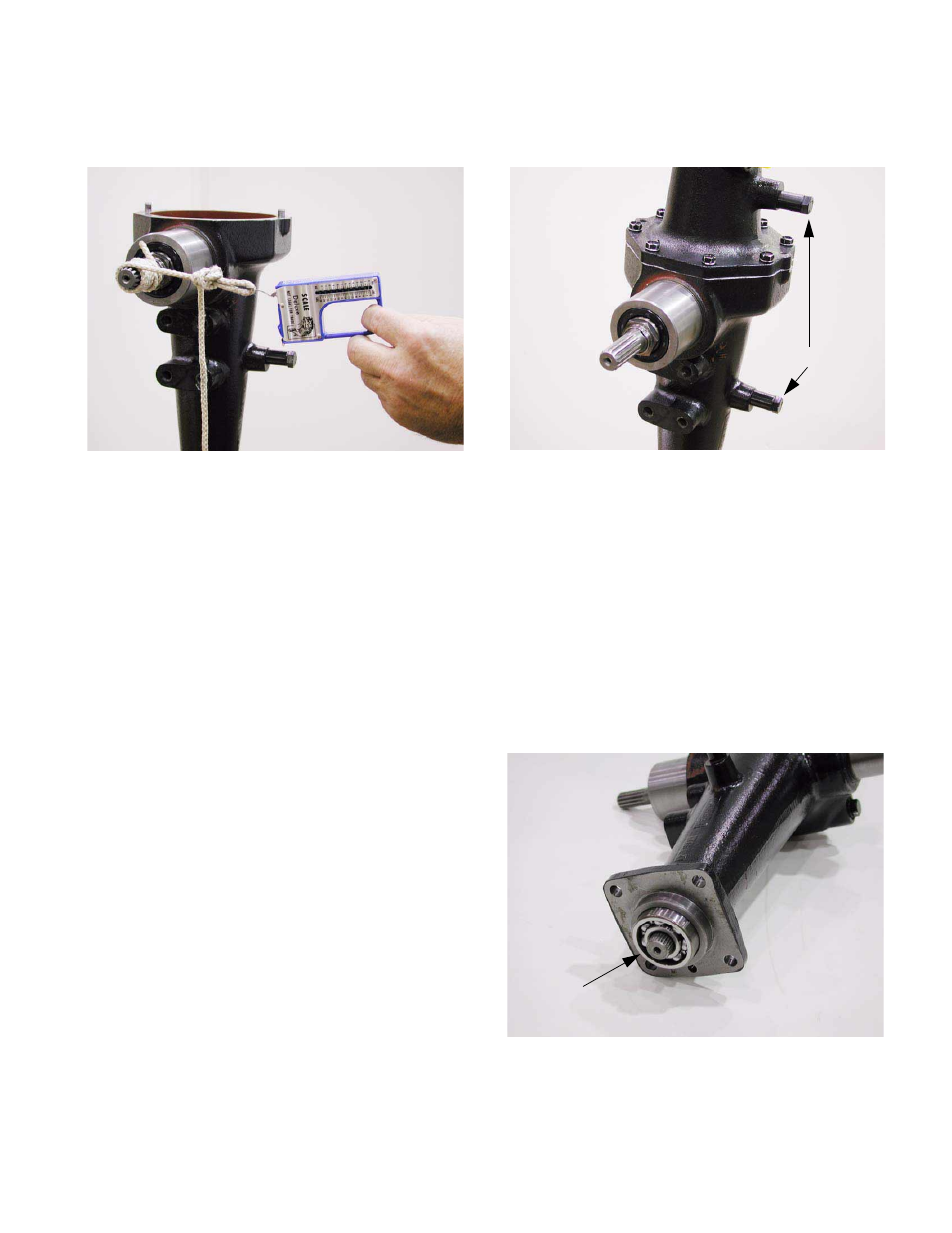
8.36. Tie a loop in the bitter end of the twine and use
this to attach a pull scale to the twine.
See Figure 8.36.
8.37. Use the pull scale to check the drag on the drive
pinion.
8.38. Tighten the pinion stake nut until a force of 22.5-
31.5 lbs. (98-137 N) is required to start the drive
pinion rotating.
8.39. Stake the pinion nut at this point.
8.40. Install the differential and axle shaft assemblies
with required number of shims.
8.41. Apply a thin bead sealant to the mating surface
of the right axle housing.
8.42. Apply thread locking compound such as Loctite
242 the threads of the bolts that will be used to
hold the axle housings together.
8.43. Position the left axle housing, using the dowel
pins in the right axle housing for alignment.
See Figure 8.43.
NOTE: Both travel stops should face in the
same direction.
8.44. Install the bolts that secure the two housings
together. Tighten them to a torque of 21-26 ft-lb.
(28.5-36.3 N-m) using a 12mm socket.
NOTE: Allow Sealant to cure for 24 hours before
filling the axle with gear lube.
8.45. Install the axle end bearings on each axle.
See Figure 8.45.
Figure 8.36
Figure 8.43
Travel Stops
Axle End Bearing
Figure 8.45