Cub Cadet 7000 Series User Manual
Page 96
7264 Four Wheel Drive Axle Assembly Removal and Disassembly
6 - 122
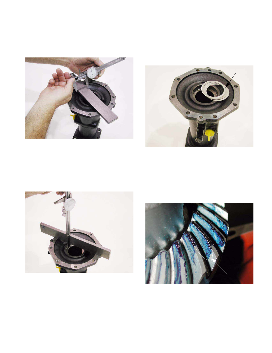
8.15. Determine the depth of the bearing bore in the
left axle housing using the following steps:
8.16. Measure and record the width of the machined
bar stock. See Figure 8.16.
8.17. Place the machined bar stock on the mating sur-
face of the left axle housing so that it spans the
bearing bore.
8.18. Measure and record the depth of the bearing
bore from the top edge of the machined bar
stock. See Figure 8.18.
8.19. Subtract the width of the machined bar stock
from the depth of the bearing bore as measured
from the top edge of the machined bar stock.
This will yield an accurate measurement of the
depth of the bearing bore.
8.20. Compare the depth of the bearing bore in the left
axle housing to the height of the outboard differ-
ential bearing above the mating surface of the
right axle housing to determine the total amount
of shimming that will be required to achieve zero
end play. See Figure 8.20.
8.21. Remove the differential bearing centering tool.
8.22. Carefully remove the axles and differential
assembly from the right axle housing.
8.23. Examine the contact pattern that is visible in the
prussian blue on the ring gear. See Figure 8.23.
Figure 8.16
Width of
Machined
Bar Stock
Figure 8.18
Machined Bar Stock
+
Depth of Bore
Figure 8.20
Shims
Left Axle Housing
Figure 8.23
Ring Gear Pattern
Ideal Contact Patch