7264 compact tractor – Cub Cadet 7000 Series User Manual
Page 51
6 - 57
7264 Compact Tractor
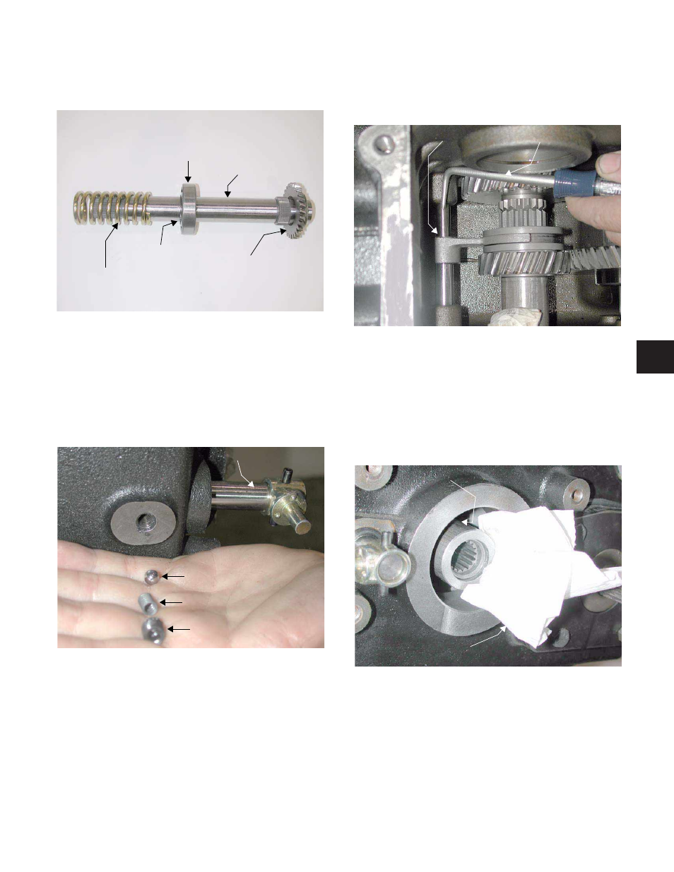
14.28. Inspect all components for wear or damage. See
Figure 14.28.
14.29. Inspect the needle bearing at the rear of the
drive shaft for damage or wear.
15.
TWO SPEED ACTUATOR SHAFT:
15.1. Remove the two speed cupped set screw from
the transmission housing using a 5/32” Allen
wrench. See Figure 15.1.
NOTE: Loctite™ the threads and apply light ten-
sion to the detent ball during assembly.
15.2. Remove the detent spring from the transmission
housing using a small Allen wrench.
15.3. Remove the detent ball from the transmission
housing using a stick magnet and a small Allen
wrench.
Figure 14.28
Compression Spring
Retaining Ring
Ball Bearing
Input Shaft
28T Auxiliary
Drive Pinion Gear
Figure 15.1
Cupped Set Screw
Detent Spring
Detent Ball
2 Speed Actuator Shaft Assembly
15.4. Remove the rotor clip securing the two speed
yoke in position using a 90° extractor tool. See
Figure 15.4.
15.5. While holding the two speed yoke in place,
remove the two speed actuator shaft.
15.6. Remove the two speed yoke.
16.
MOTOR SHAFT ASSEMBLY:
16.1. Remove the shop cloth securing the motor shaft
assembly in position. See Figure 16.1.
Figure 15.4
Rotor Clip
90° Extractor Tool
Figure 16.1
Remove the Shop Cloth
Motor Shaft Assembly
6