7264 compact tractor – Cub Cadet 7000 Series User Manual
Page 66
7264 Compact Tractor
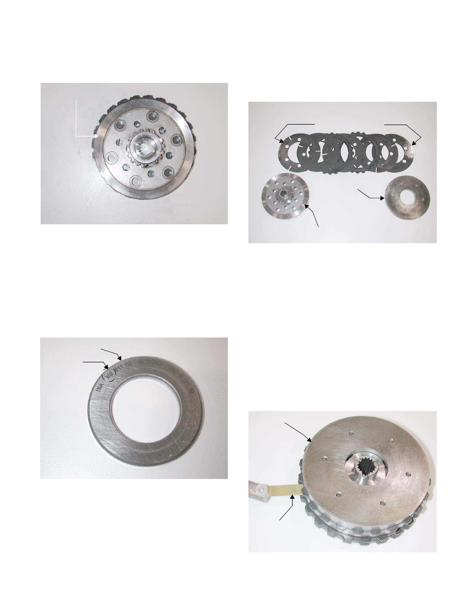
24.14. Inspect the top of the rotor surface for wear or
damage. See Figure 24.14.
24.15. Remove the rotor from the clutch assembly and
inspect the bottom surface for wear or damage.
24.16. Inspect the thrust washer running surface for
wear or damage.
NOTE: The WS thick thrust washer has a cham-
fer on its outer edge that must face away from
the thrust bearing, towards the brake clutch
assembly, during assembly. See Image Below.
24.17. Remove each bolt driven steel brake clutch disk
and each external brake clutch disk, one at a
time, inspecting them for wear or damage. See
Figure 24.17.
NOTE: There are two bolt driven steel brake
clutch disks that start the brake clutch series,
and two bolt driven steel brake disks that end the
brake clutch series on early production units.
24.18. Inspect the rear cover.
24.19. Clean the rear cover using a cleaning pad and
scraper.
24.20. Assemble the pto clutch assembly in the reverse
order above.
NOTE: There are six spacers that are matched
at the factory to give the PTO clutch assembly
the proper air gap. These parts are not available.
See Image Below.
Figure 24.14
Rotor Surface
WS Thrust Washer with Chamfer
WS
Thick Thrust Washer
Figure 24.17
Brake Clutch Disks
Rotor Surface
Top Housing
PTO Clutch Assembly Air Gap is Set at the Factory
PTO Clutch Assembly
Feeler Gauge
Checking Air Gap
6 - 72