Cub Cadet 7000 Series User Manual
Page 100
7264 Four Wheel Drive Axle Assembly Removal and Disassembly
6 - 126
9.16. Apply a small bead of sealant to the mating sur-
face of the left axle housing flange.
9.17. Apply thread locking compound such as Loctite
242 to the threads of each bolt that will be used
to hold the final drive assembly to the axle.
9.18. Position the left side final drive housing on the
left end of the axle, and secure it with four bolts.
9.19. Tighten the bolts using a 14mm socket.
See Figure 9.19.
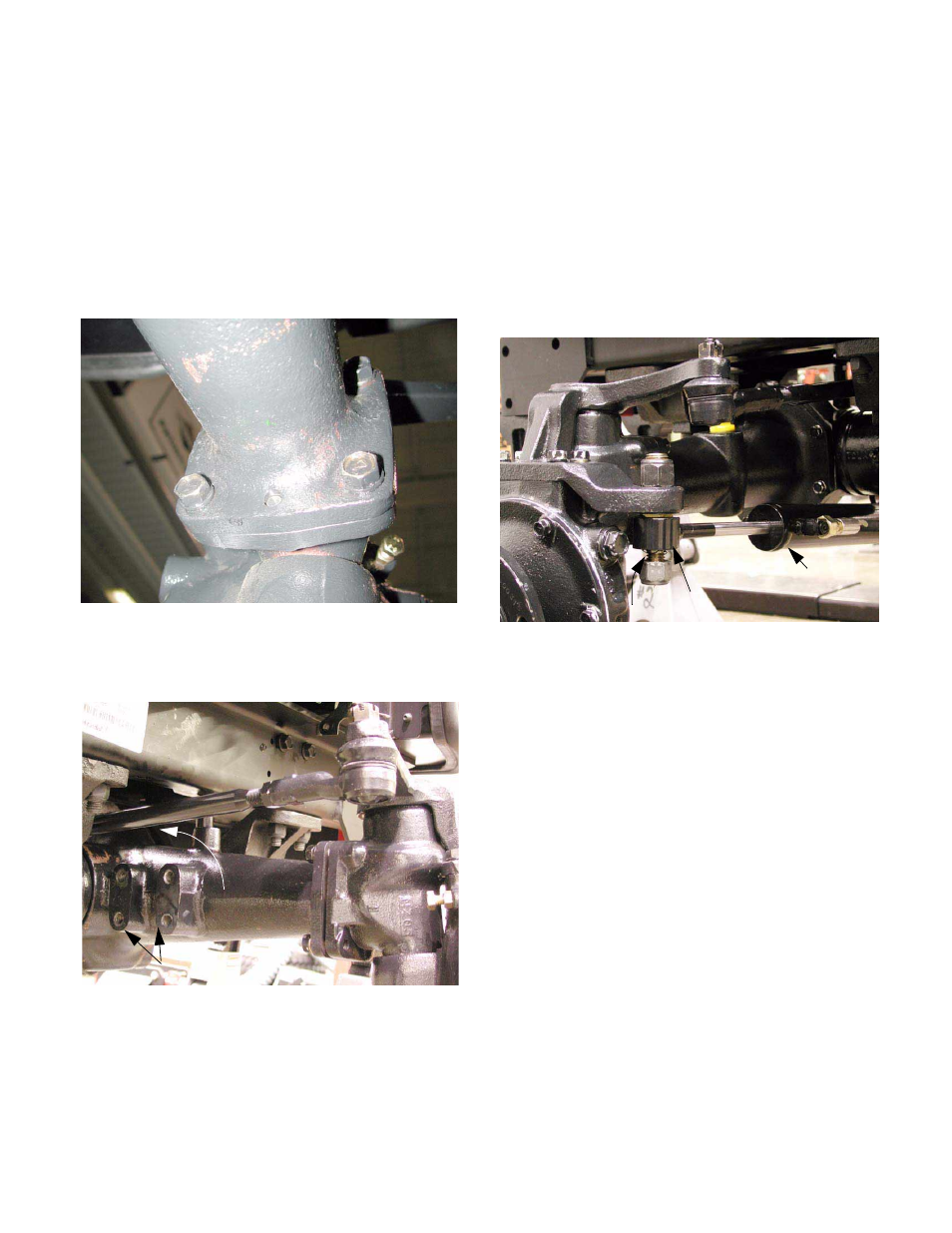
9.20. Install the right side final drive assembly in the
same manner as the left side. See Figure 9.20.
NOTE: If the tie rod was not disconnected from
the steering arm during the removal process, it
must be inserted between the axle and the
frame, in front of the rear axle mounting bracket
as the final drive assembly is installed.
9.21. Install the left tie rod end to the left steering arm.
9.22. Tighten the nut on the tie rod end to a torque of
22-26 ft-lbs using a 19mm socket, then secure it
with a new cotter pin.
9.23. Cut the cable tie used to temporarily hold the
steering cylinder out of the way, and lower it gen-
tly to the floor.
9.24. Install the eyelet at the end of the steering ram
onto the Stud beneath the left steering arm.
See Figure 9.24.
9.25. Install a new locking nut on the stud, and tighten
it to a torque of 67-85 ft-lbs (91-115 N-m) using a
pair of 24 mm wrenches.
9.26. Apply thread locking compound such as Loctite
242 to the bolts that will be used to hold the
steering cylinder bracket to the axle.
Figure 9.19
Insert Tie Rod
Figure 9.20
Machined Boss to Mount
Steering Cylinder and Bracket.
Figure 9.24
Steering
Cylinder
Eyele
t
Stud