7264 adjustments – Cub Cadet 7000 Series User Manual
Page 105
7264 Adjustments
1.22. Release the parking brake.
1.23. Connect the ferrule on the end of the brake link
to the brake arm. See Figure 1.23.
1.24. Secure the ferrule with a hairpin clip.
1.25. Start the tractor on the stands, and test the oper-
ation of the linkages and Safety features.
1.26. Install the tunnel cover, securing it with the two
screws and four bolts previously removed.
1.27. Secure the foot pads with the push in fasteners.
1.28. Lower the tractor to the ground and test drive it
in a safe area before returning it to service.
NOTE: If correct linkage adjustment does not
result in correct function of the hydrostatic trans-
mission, refer to the TRANSMISSION section of
this manual.
NOTE: There is some angle adjustment avail-
able where the pedal mounts to the hydro con-
trol arm. This is not the hydro control
adjustment. The pedal adjustment may be
changed to suit operator preference as long as it
does not impede the full travel of the hydro con-
trol linkage.
NOTES_____________________________________
2.
BRAKE ADJUSTMENT
2.1.
Turn the engine OFF.
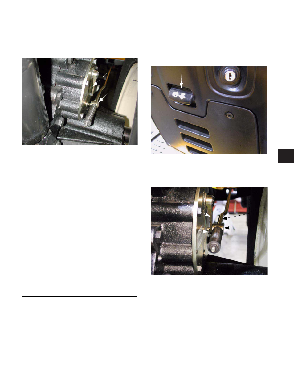
2.2.
Depress the brake pedal and set the parking
brake. See Figure 2.2.
2.3.
Locate the brake assemblies on the each side of
the transmission housing. See Figure 2.3.
NOTE: This is where brake adjustment is mea-
sured. Do not attempt to adjust the brake using
the nut that keeps tension on the spring. The
nut is bottomed-out against a shoulder on the
brake link. It cannot be tightened to increase
brake pressure. Loosening the nut only
increases the travel required to apply the brake.
Figure 1.23
Ferrule
Brake Arm
Figure 2.2
Parking Brake
Figure 2.3
Brake Link
Ferrule
Brake Lever
Hairpin Clip
6
6 - 131