7264 compact tractor – Cub Cadet 7000 Series User Manual
Page 31
6 - 37
7264 Compact Tractor
27.3. Remove the brake drums. See Figure 27.3.
28.
AXLE ASSEMBLIES:
28.1. Place a suitable drain container under the left
axle assembly.
28.1. Remove all the perimeter hex cap lock screws
securing the left axle assembly to the transmis-
sion using a 1/2” socket.
NOTE: Loctite™ the threads and torque them
between 360 and 420 In. Lbs.
28.2. Remove the left axle assembly.
28.3. Perform the above steps to remove the right axle
assembly.
Figure 27.3
Brake Drum Housing
29.
TRANSMISSION ASSEMBLY TO ENGINE
STAND MOUNTING:
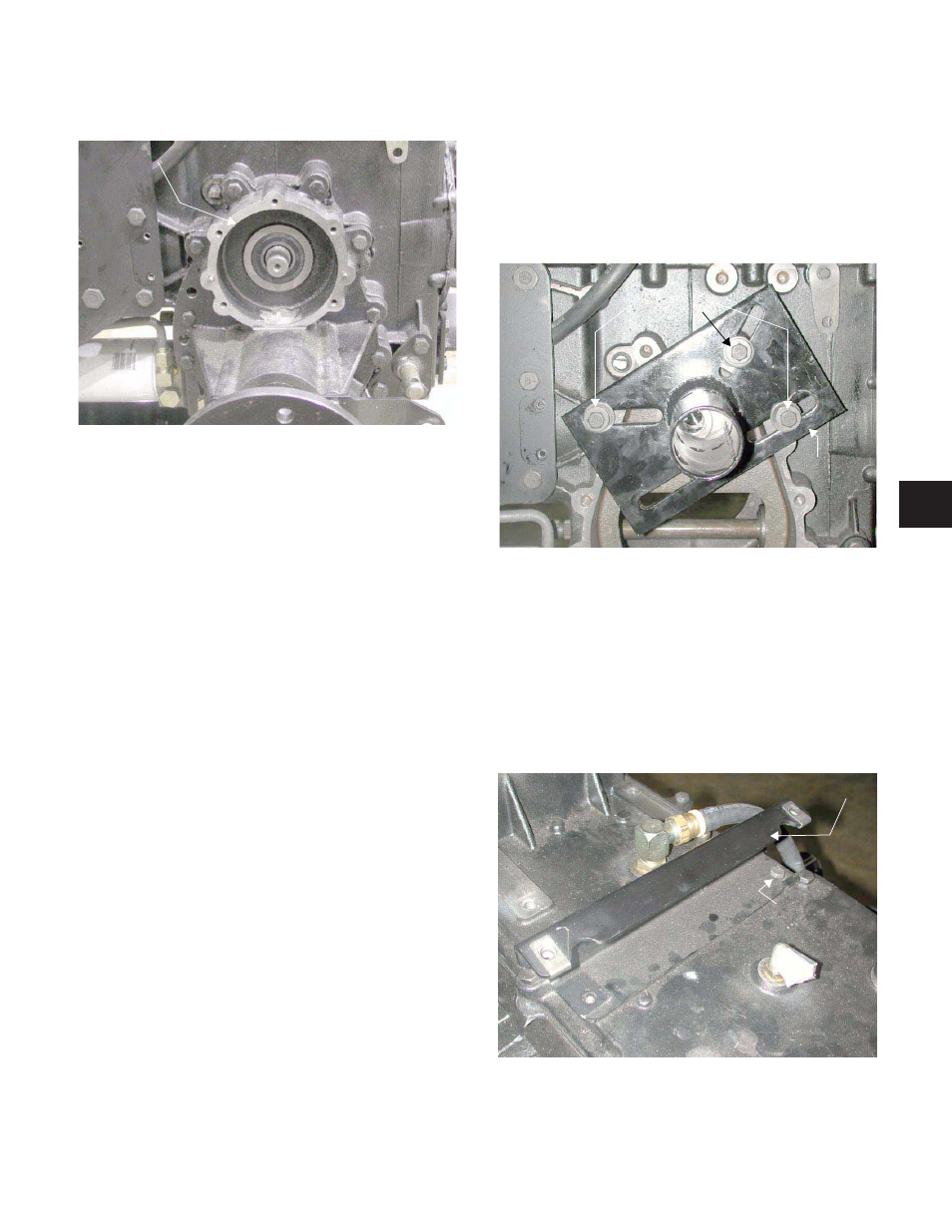
29.1. Secure the engine stand mounting bracket to the
left side of the transmission housing with the
axle housing hardware removed earlier, and
Factory School supplied flat washers and spac-
ers using a 5/8” socket. See Figure 29.1.
NOTE: Make certain the engine stand mounting
bracket is centered to the transmission housing,
and the differential lock actuator shaft is not
blocked.
30.
REAR SEAT SUPPORT BRACKET:
30.1. Remove the remaining hex cap screw securing
the rear seat support to the transmission hous-
ing cover using a 1/2” socket. See Figure 30.1.
NOTE: Loctite™ the threads and torque them
between 160 and 200 In. Lbs. during assembly.
Figure 29.1
Engine Stand
Mounting Bracket
Hardware
Axle Housing
Figure 30.1
Rear Seat Support
Hex Screw
6