Cub Cadet SLTX1000 Series User Manual
Page 90
LTX Tractors
84
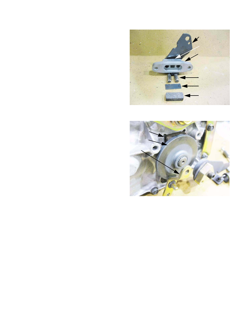
6.
Inside the brake yoke;
•
A steel backing plate fits between the friction
pad and the actuator pins.
•
The pins fit into holes in the brake yoke hous-
ing.
•
The brake arm acts as a cam, pushing the pins
when it rotates.
•
A small compression spring pushes the cam
arm away from the pins, helping to release the
brake.
7.
With the brake yoke removed, the brake rotor floats
on a splined brake shaft. See Figure 5.69.
•
The bypass linkage must be removed to take
the rotor off.
•
The flat side goes in, the collar faces out.
•
A second brake pad fits into a recess behind
the rotor.
8.
Assembly notes:
•
If any lubricant is used on the pins or between
the brake shaft and the rotor, apply it VERY
sparingly.
•
Apply a small amount of thread locking com-
pound such as Loctite 242
TM
(blue) to the
threads of the brake yoke bolts.
•
Tighten the brake yoke bolts to a torque of 80 to 120 in-lbs. (9 to 14 N-m).
9.
Adjust and test the brakes after any work on brake system.
Figure 5.68
Brake arm
Spring
Brake yoke
Friction pad
Backing plate
Actuator pins (2)
Figure 5.69
Brake pad
Brake rotor
bypass
arm