Cub Cadet SLTX1000 Series User Manual
Page 129
CVT DRIVE AND BRAKE SYSTEM
123
F.
Withdraw the belt from the front of the tractor.
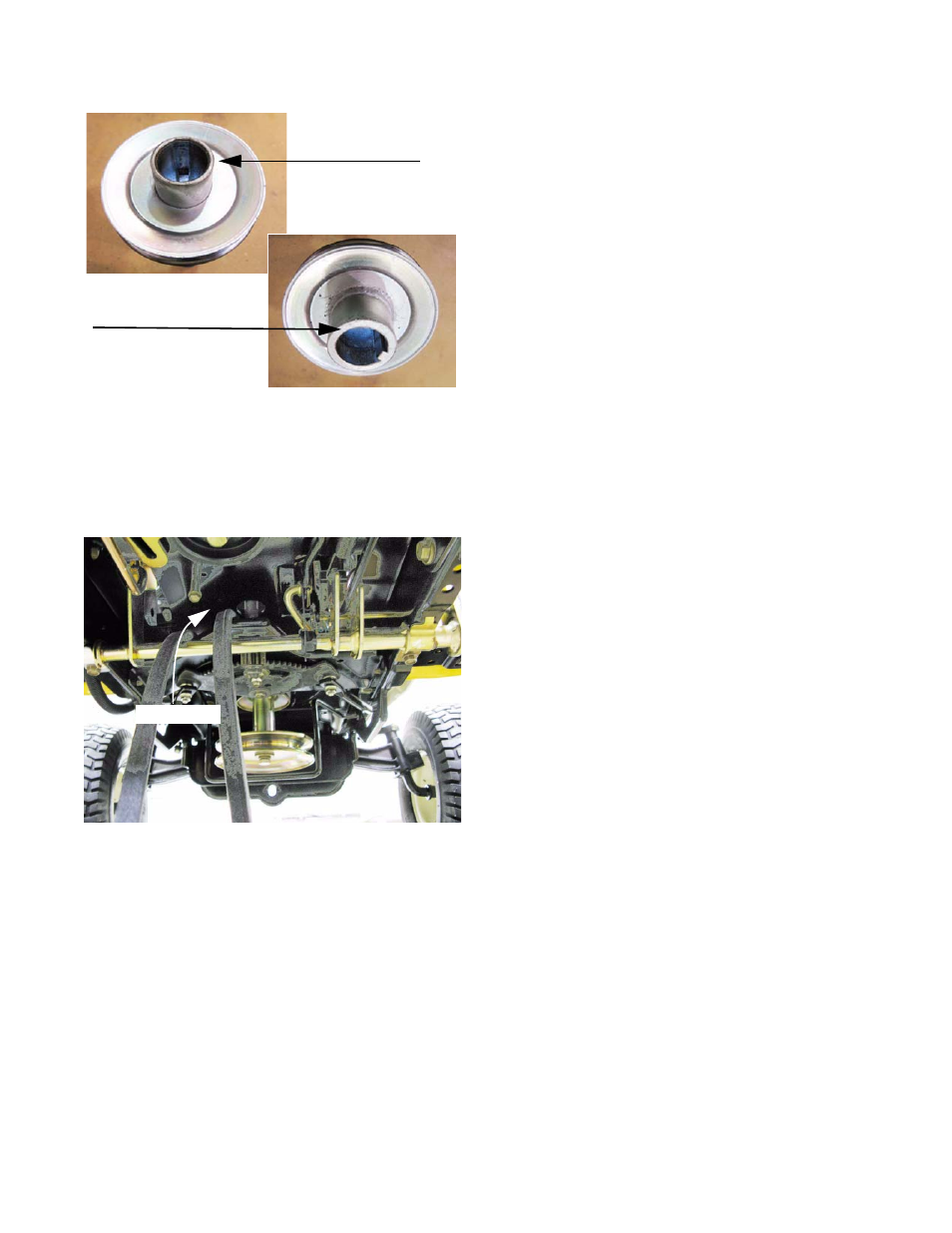
NOTE: The flat edge of the crankshaft pulley faces the
electric PTO clutch. The end with the inside diame-
ter chamfered goes against the fillet near the base
of the crankshaft. See Figure 6.72.
NOTE: If the drive belt failed prematurely, identify and cor-
rect the cause of the failure before installing a new
belt.
6.
Install the new belt by reversing the steps used to
remove it.
Belt installation notes:
• Install only correct OEM belts. Incorrect belts may
cause problems that effect the performance and/or
safety of the tractor.
• Apply a small amount of anti-seize compound to
the engine crankshaft before installing the crank-
shaft pulley.
• Apply a small amount of thread locking compound
such as Loctite 271
TM
(red) to the threads of the
crankshaft bolt.
• Tighten the crankshaft bolt to a torque of 36-50 ft-
lbs (50-68 N-m).
• The belt is routed to the left of the steering shaft,
and the foremost keeper pin goes between the
runs of the belt. See Figure 6.73.
7.
Thoroughly test the operation of the drive system and
all safety features before returning the tractor to ser-
vice.
Figure 6.72
Top of
crankshaft pulley
Bottom of
crankshaft pulley
Figure 6.73
Belt routing