Control arm and friction pack, Disassembly, Inspection – Cub Cadet SLTX1000 Series User Manual
Page 255: Assembly
310-0510 IHT
17
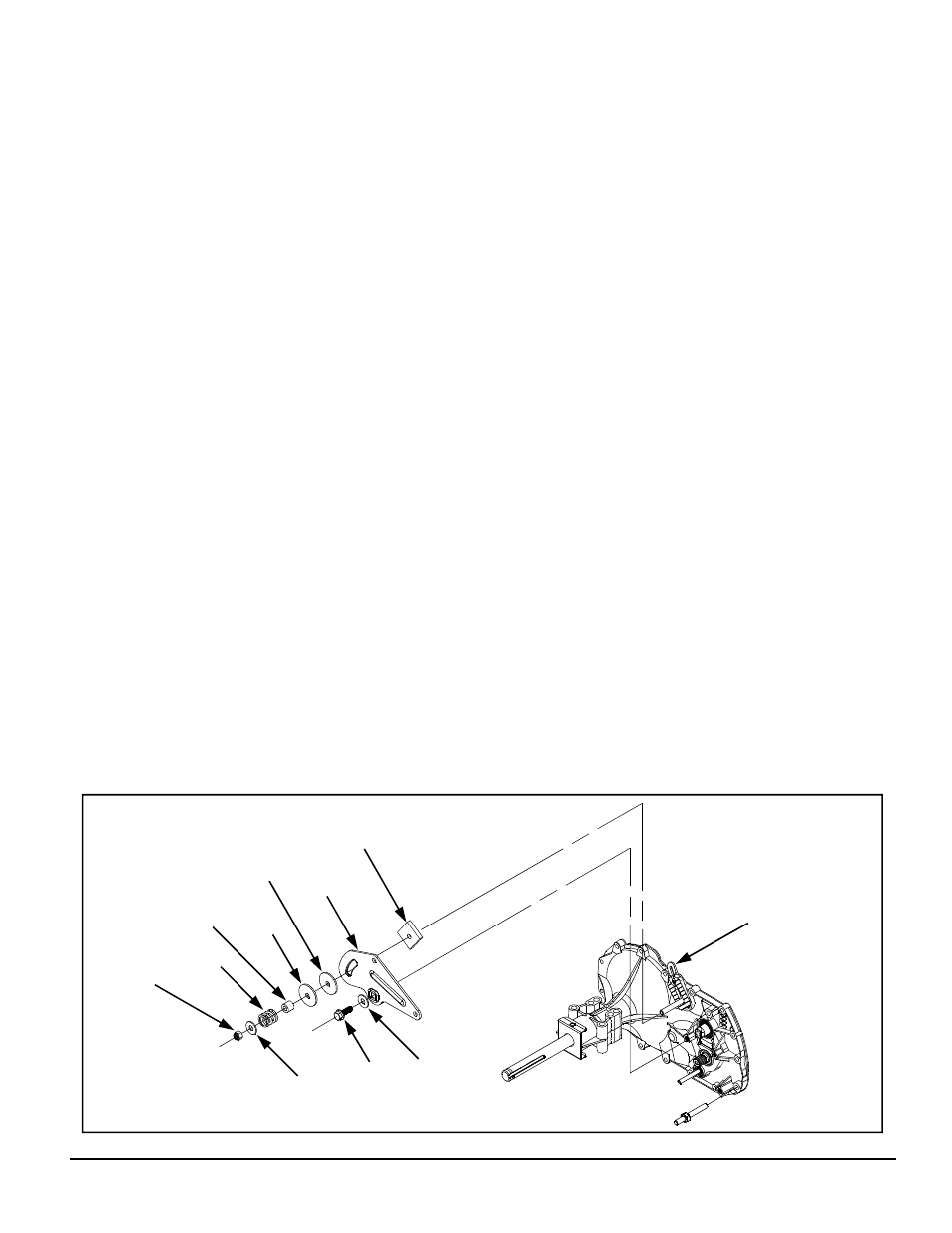
CONTROL ARM AND FRICTION PACK
Refer to Figure 9.
DISASSEMBLY
1. Remove the brake assembly. See page 16.
2. Loosen and remove the friction pack lock
nut (80), flat washer (73), spring (78),
spacer (79), washer clip (82) and puck (77).
Discard the lock nut (80).
3. Remove the hex head screw (16) from the
directional control.
4. Remove the flat washer (73) and control
arm (18).
5. Remove the inner wedge puck (90).
6. Removal of the friction pack wedge (81)
should not be necessary. Note: If it is re-
moved, mark the orientation of the wedge
for ease in reassembly.
7. If necessary, remove and replace the fric-
tion pack stud (76).
INSPECTION
1. Inspect the friction pack assembly compo-
nents for wear or damage.
2. Inspect the control arm for wear or damage.
3. Inspect the inner wedge puck (90).
4. Inspect the friction pack stud (76) for wear
or damage.
ASSEMBLY
1. Install the friction pack stud (76), if removed.
Torque according to specifications in Table
5.
2. If previously removed, install the friction
pack wedge (81) and self tapping bolt (88).
Refer to Table 5 for bolt torque specifica-
tions. Use the marks made during disas-
sembly to reposition the wedge properly.
3. Install the inner wedge puck (90).
4. Install the control arm (18).
5. Install the flat washer (73) and control arm
screw (16). Note: Remember to apply
thread adhesive to the screw threads before
installation. Refer to Table 5 for screw
torque specifications.
6. Install the puck (77), washer clip (82),
spacer (79), spring (78), flat washer (73)
and a new lock nut (80). Adjust the friction
pack according to instructions on page 13.
7. Install the brake assembly. See page 16.
Figure 9. Control Arm & Friction Pack
73
78
80
79
82
77
16
73
18
90
76, 81, 88