Cub Cadet SLTX1000 Series User Manual
Page 65
HYDRO. DRIVE AND BRAKE SYSTEM
59
6.
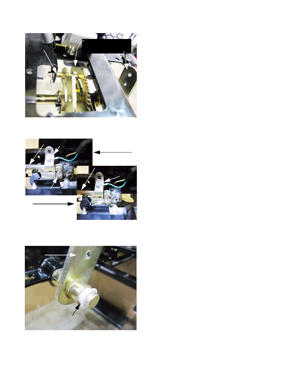
Check the drive control linkage. See Figure 5.7.
6a.
The travel limit pin fits into the curved slot in the
drive pedal latch plate. The pedal bracket
should have enough travel for the pin to hit both
ends of the curved slot when the pedal is
moved through the full range of its travel.
6b.
Some lost motion is built into the linkage so that
there is a “dead” range as the pedal moves
from neutral to reverse. See Figure 5.8.
• This dead spot allows the reverse safety switch to
act before the tractor actually begins to move
backward.
• It is normal to have 1-1/8” play at the Forward
pedal or 1” play at the Reverse pedal in this dead
range.
6c.
The most likely causes for additional lost motion
that would effect the ground speed of tractor
are: See Figure 5.9.
• The drive pedal itself being loose on the bracket.
• Worn plastic bushings between the drive pedal
bracket and the brake cross-shaft.
Figure 5.7
Travel limit pin
Drive pedal latch plate
Drive pedal bracket
Figure 5.8
Lost motion slot;
Neutral or Forward
Reverse
Lost motion slot;
Drive control rod
Drive control rod
Lost motion link
Lost motion link
Connector pin
Connector
pin
Figure 5.9
Plastic bushing
Pedal mounting
bracket