Cub Cadet SLTX1000 Series User Manual
Page 145
CVT DRIVE AND BRAKE SYSTEM
139
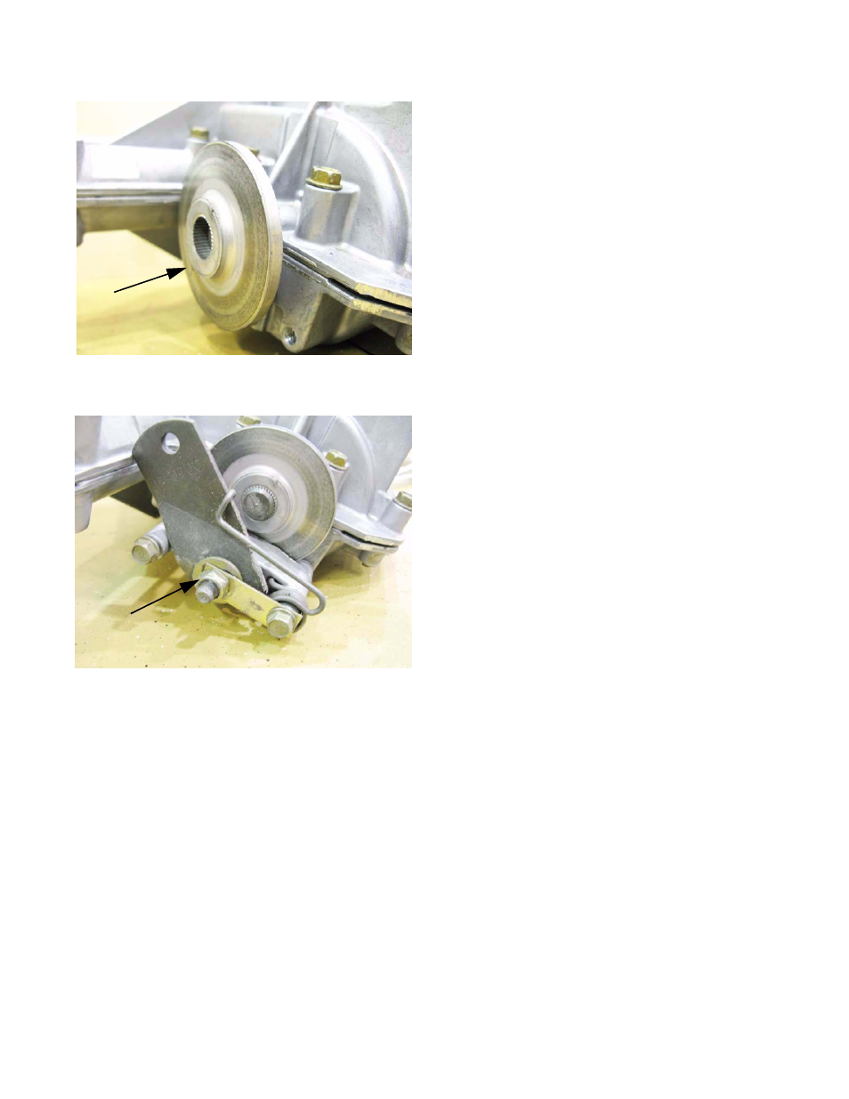
35c. Install the brake rotor, with the flat side facing
the transaxle housing. See Figure 6.110.
35d. Install the brake yoke to the transaxle, being
careful not to let the friction pad or backing plate
fall out of place.
35e. Tighten the brake yoke screws to a torque of
90-135 in-lbs. (10-15 N-m).
35f. Set the clearance between the pads and rotor
to 0.010-0.015” (0.25-0.38mm) using the
adjusting nut on the brake yoke.
See Figure 6.111.
35g. Re-hook the brake spring to the brake arm
35h. Re-install the shift rod pillow block.
35i. Give the transaxle a final spin-test before instal-
lation.
Figure 6.110
Brake rotor
Figure 6.111
Adjustment nut
This manual is related to the following products: