Start circuit, Electrical system – Cub Cadet SLTX1000 Series User Manual
Page 163
Electrical System
157
Start Circuit
Turning the key to the START position:
•
spins the starter motor
•
enables the ignition
•
energizes the afterfire solenoid
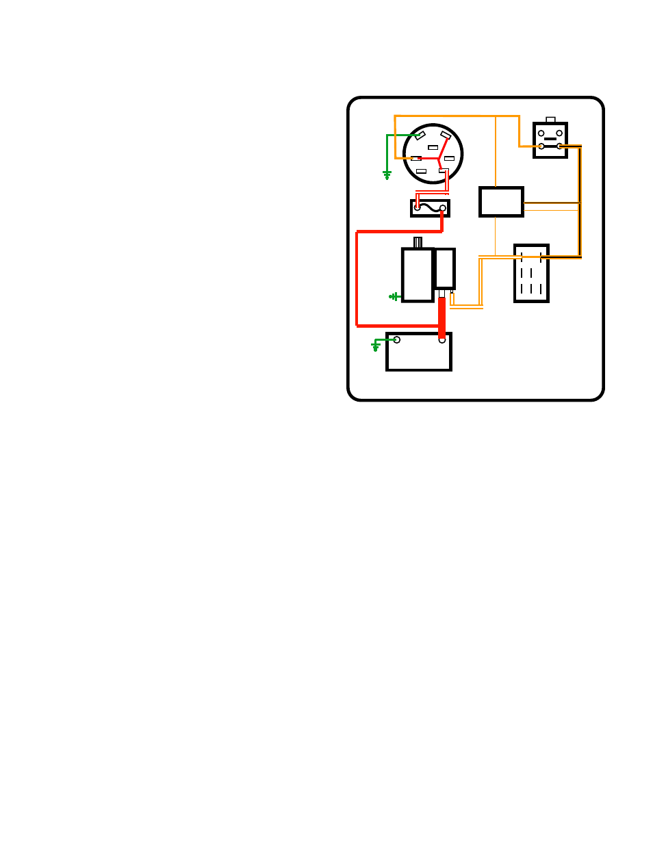
Looking at the circuit that sends power to the starter
motor: See Figure 7.21.
1.
When the key switch is in the START position, bat-
tery power is passed from the B terminal to the S
terminal.
2.
Power goes from the key switch S terminal to the
brake switch (N.O.) contacts. (orange wire)
2a.
If the brake is off, the switch plunger will be up
and the (N.O.) contacts will be open. The sys-
tem monitor will measure open circuit voltage,
illuminating the brake symbol.
2b.
If the brake is depressed, the switch plunger
will be depressed, and the (N.O.) contacts will
be closed. Power will be passed along to the
PTO switch.
3.
When the key is in START, and the brake is
depressed, power will continue to the A-N.C. termi-
nal (electric PTO) or to one of the (N.C.) terminals
(manual PTO) of the PTO switch (orange/black
trace).
3a.
If the PTO switch is on, the (N.C.) terminal on the A set of contacts will not connect to anything. The sys-
tem monitor will measure open circuit voltage, illuminating the PTO symbol.
3b.
If the PTO switch is off, the (N.C.) terminal on the A set of contacts will be connected to the COM termi-
nal on the A set of contacts. Power will be passed along to the trigger terminal on the starter solenoid.
4.
When the following conditions are met:
•
Key to START
•
Brake pedal is depressed
•
PTO off
The starter solenoid trigger terminal will receive power (orange wire).
5.
When the starter solenoid trigger terminal receives power two things happen:
A.
A set of contacts close inside the solenoid allowing the power to pass through to the starter motor.
B.
The solenoid pushes the bendix gear out so that it may engage the ring gear of the flywheel.
'
!
,
3
!
-
"
+EY
"ATTERY
.%'
0/3
&USE
'RND
'ROUND
04/
#/
-
./
.#
3YSTEM
-ONITOR
!
"
#
.#
./
"RAKE
6WDUWHU0RWRU
*URXQG
6ROHQRLG
Figure 7.21