Cub Cadet SLTX1000 Series User Manual
Page 86
LTX Tractors
80
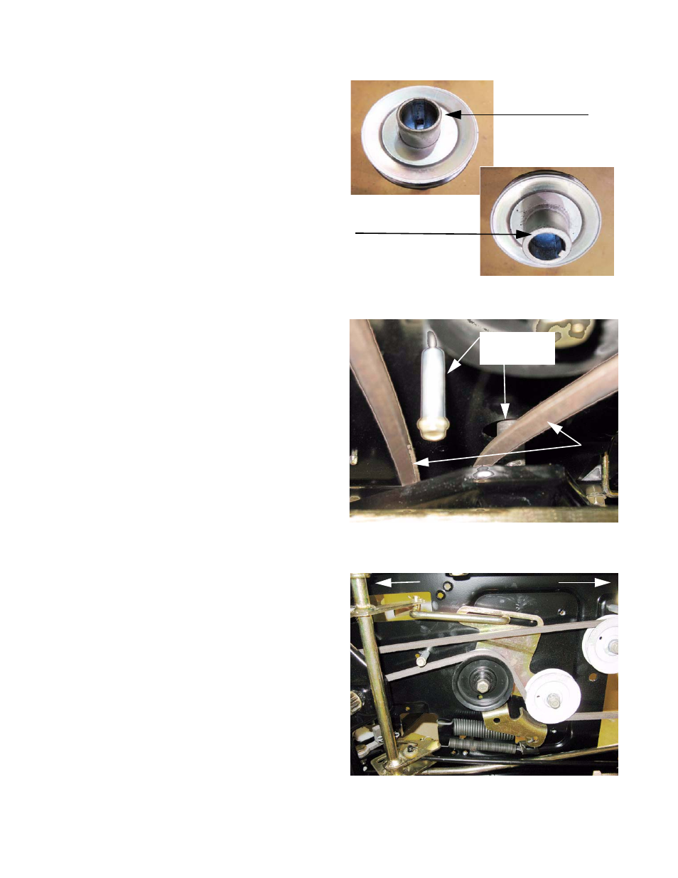
NOTE: The flat edge of the crankshaft pulley faces
the electric PTO clutch. The end with the
inside diameter chamfered goes against the
fillet near the base of the crankshaft.
See Figure 5.58.
11.
If the drive belt failed prematurely, identify and cor-
rect the cause of the failure before installing a new
belt.
12.
Install the new belt by reversing the steps used to
remove it.
Belt installation notes:
•
Install only a correct OEM belt. Incorrect belts
may cause problems that effect the perfor-
mance and/or safety of the tractor.
•
Apply a small amount of anti-seize compound
to the engine crankshaft before installing the
crankshaft pulley.
•
Apply a small amount of thread locking com-
pound such as Loctite 271
TM
(red) to the
threads of the crankshaft bolt.
•
Tighten the bolt to a torque of 36-50 ft-lbs. (50-
68 N-m).
•
The belt is routed to the left of the steering
shaft, and the fore-most keeper pin goes
between the runs of the belt. See Figure 5.59.
•
Correct routing. See Figure 5.60.
•
Tighten the nut that holds the fan and pulley to
the input shaft to a torque of 30-43 ft-lbs (41-58
N-m).
13.
Thoroughly test the operation of the drive system
and all safety features before returning the tractor to
service.
Figure 5.58
Top of
crankshaft pulley
Bottom of
crankshaft pulley
Figure 5.59
Belt keeper pin
Steering shaft
Belt
Looking forward from under the tractor
Figure 5.60
Front Back