Indications that a transaxle is not warrantable, Brake adjustment – Cub Cadet SLTX1000 Series User Manual
Page 103
CVT DRIVE AND BRAKE SYSTEM
97
Indications that a transaxle is not warrantable
Anything that would indicate misuse, abuse, neglect, accident, improper maintenance, alteration, vandalism, theft,
fire, water or damage because of other peril or natural disaster will render the transaxle non-warrantable even though
it is within the normal warranty period.
Typical indicators of a void warranty would be:
•
The normal warranty is for 3 years or 120 hours, whichever comes first. Beyond 120 hours of use, the
tractor is out of warranty
•
Abnormally high wear indicators for the age of the tractor (usually consistent with high hours of usage). As
an example, if the tires are completely worn-out on a tractor that is 6-months old, it is reasonable to think
it has been used pretty heavily even if the hour meter has been unplugged.
•
Bent axle, broken housing, or other obvious signs of impact damage
•
Contaminated fluid or low fluid
•
Damage to the cooling fan
•
Indication that the tractor has been overloaded.
Brake adjustment
1. Test the operation of the brakes: See Figure 6.8.
1a.
Put the transaxle in neutral.
1b.
Set the parking brake by depressing the brake/
clutch pedal and pushing-down on the parking
brake/cruise control lever.
1c.
Attempt to push the tractor. If it can be pushed
by hand without skidding a rear wheel, check
and adjust the brakes.
1d.
Release the parking brake.
1e.
Attempt to push the tractor again. If it cannot be
pushed with little effort, check and adjust the
brakes.
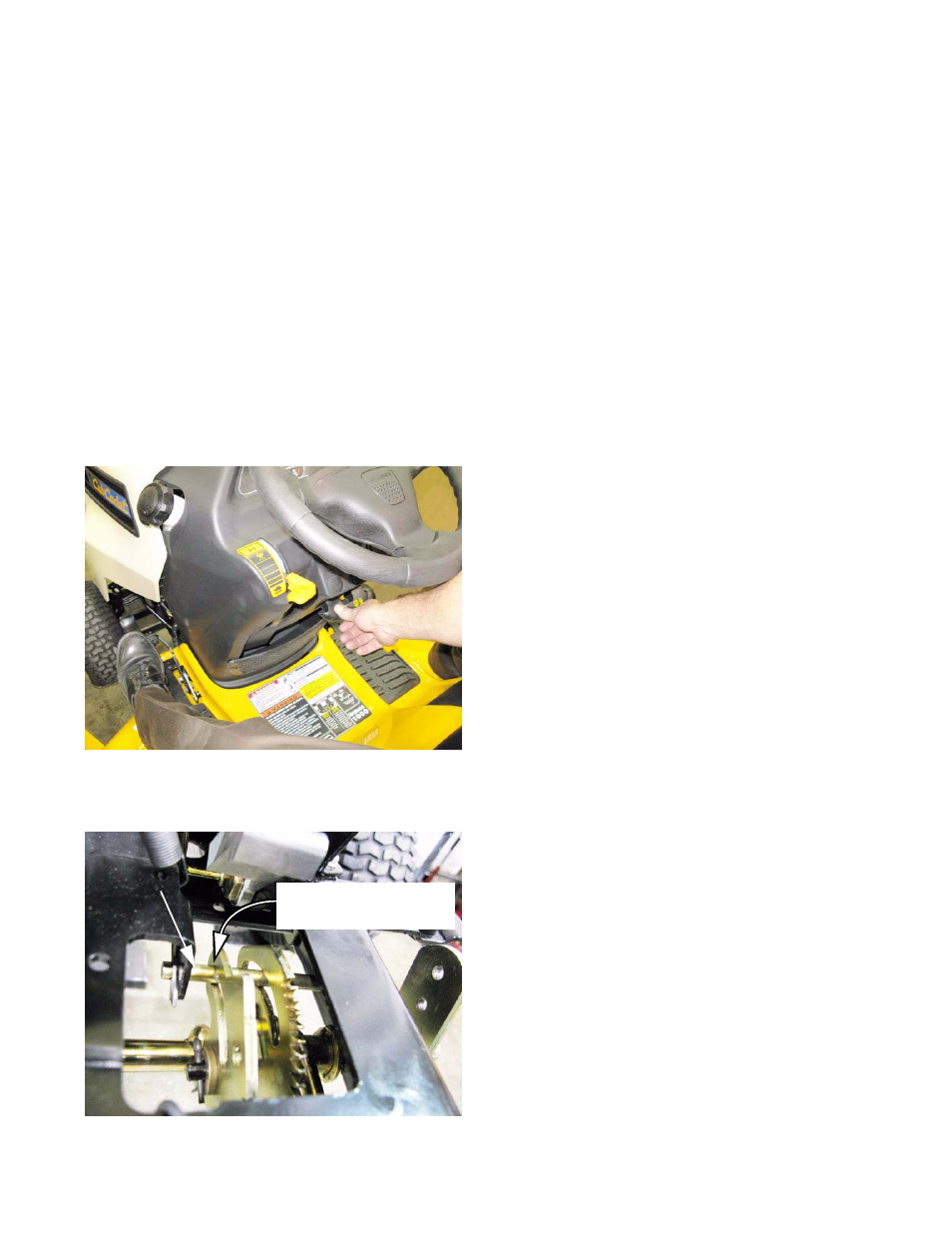
2.
Visually inspect the linkage to confirm that it functions
properly. See Figure 6.9.
• Beneath the floor panel, on the right side of the
tractor there are two semi-circular latch plates.
• The outer latch plate rotates with the drive control
pedals. The inner latch plate rotates with the
clutch/brake pedal.
2a.
With the clutch/brake pedal fully released:
• The travel limit pin should be resting against the
front of the curved slot. See Figure 6.9.
Figure 6.8
Figure 6.9
Travel limit pin
Clutch/brake latch plate:
fully released position