Cub Cadet SLTX1000 Series User Manual
Page 144
LTX Tractors
138
21.
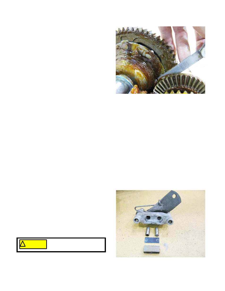
Press the differential and the reverse gears as close
together as they will go while remaining properly
seated in the housing.
22.
Confirm that there is at least 0.030” (0.762mm)
between the rivet heads on the differential and the
back side of the reverse gear. See Figure 6.108.
23.
Collective axle end play (the amount one axle shaft
moves when the opposite axle is pushed) should be
between 0.010”-0.080” (0.25-2.0mm).
24.
Adjust the shims as necessary to achieve these two
conditions.
25.
Install the shift fork.
26.
Install the top of the transaxle housing, and tighten
the perimeter screws finger-tight.
27.
Spin-test the transaxle in forward, neutral, and
reverse.
28.
Check the input shaft backlash:
28a. Engage forward gear, hold the brake spline and rotate the input shaft. The top edge of the input shaft
should rotate between 0.006”-0.014” (0.15-0.36mm).
28b. Engage reverse gear, hold the brake spline and rotate the input shaft. The top edge of the input shaft
should rotate between 0.006”-0.014” (0.15-0.36mm).
29.
Remove the top of the housing, and adjust the bevel shaft gear shims as necessary, then re-check.
NOTE: The backlash in the input shaft is a function of the amount of play between the pinion gear and the
bevel gear it is driving. Shimming a bevel gear to run nearer the pinion shaft will reduce the backlash.
Removing shims to allow more space between the pinon and bevel gears will increase the amount of
backlash.
30.
Install, or add Durina
TM
grease to a total of 20 fl.oz. (0.59 liters) in the housing.
31.
Carefully install the top of the housing, and install the 13 perimeter screws, leaving 2 empty screw holes; 1 on
each side of the brake spline.
NOTE: No sealant is necessary.
32.
Tighten the screws to a torque of 90-135 in-lbs. (10-
15 N-m).
33.
Install the detent ball, spring, and screw.
34.
Tighten the detent screw to a torque of 160-200 in-
lbs. (18-23 N-m).
35.
Assemble the brake yoke:
35a. Apply a small amount of anti-seize compound
to the brake rotor splines and to the actuator
pins in the brake yoke.
35b. Install the steel backing plate against the pins,
then place the friction pad against the backing
plate. See Figure 6.109.
Figure 6.108
Figure 6.109
! CAUTION
! CAUTION
Do not get anti-seize on the fric-
tion surfaces of the brake.