Thermcraft XST-6-0-36-3V User Manual
Page 244
Configuration
Installation and Operation Handbook
6-12
2416 Controller
Name
Description
Values
Meaning
1A
Module 1 configuration
id
Identity of module installed
rELy
Relay output
dC.OP
Non-isolated DC output
LoG
Logic/PDSIO output
SSr
Triac output
For ‘
id’ = ‘rELy’, ‘LoG’, or ‘SSr’ use this parameter table:
Func
Function
nonE
Function disabled
dIG
Digital output function
HEAt
Heating output
COOL
Cooling output
up
Open motorised valve
dwn
Close motorised valve
(Only if ‘
id’ = ‘LoG’) SSr.1
PDSIO mode 1 heating
(Only if ‘
id’ = ‘LoG’) SSr.2
PDSIO mode 2 heating
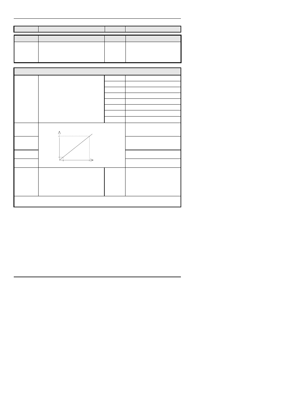
VAL.L
% PID demand signal giving
minimum output
− ‘Out.L’
VAL.H
% PID demand signal giving
maximum output
− ‘Out.H’
Out.L
Minimum average power
Out.H
Maximum average power
SEnS
Sense of output
(Only if ‘
Func’ = ‘dIG’)
nor
Normal (output energises
when TRUE, e.g program
events)
inv
Inverted (output de-
energises when TRUE, e.g.
alarms)
When ‘
SEnS’ appears, then further parameters are available. See the table on the next
page.
VAL.L
Out.H
Out.L
VAL.H
PID Demand Signal
Electrical
Output