Led as shown in, Figure 4.1 – Rockwell Automation 2098-IPD-xxx Ultra5000 Intelligent Positioning Drives Installation Manual User Manual
Page 84
Publication 2098-IN001E-EN-P — April 2002
4-4
Commissioning Your Ultra5000
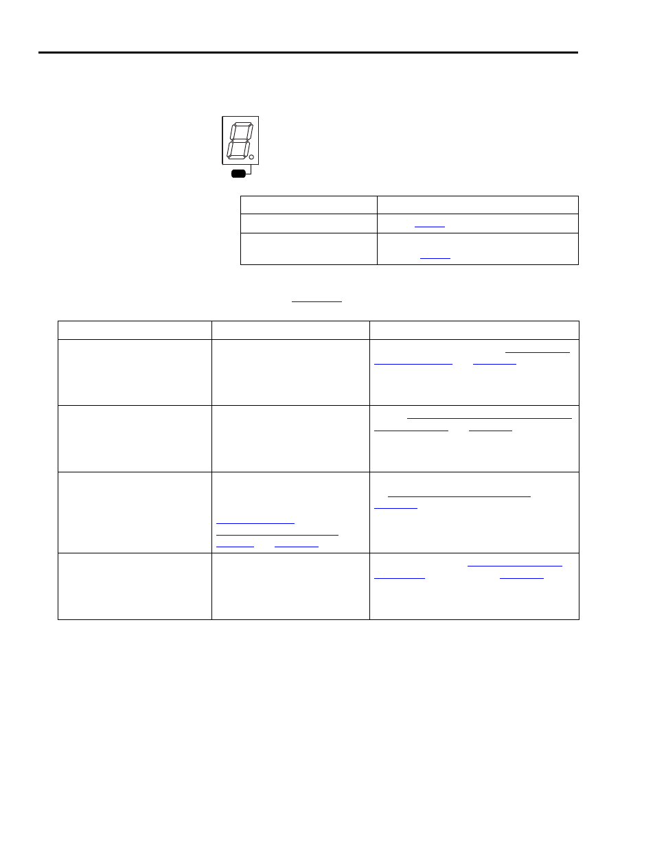
Figure 4.1
Logic Power and Status LED Display
4. Observe the front panel seven segment Status LED display as
shown in
.
If the Logic Power LED is:
Then:
ON
Go to
Not ON
Check your input power connections.
Repeat
Status
PWR
If the Status LED display on your: Is:
Then:
2098-IPD-xxx,
2098-IPD-HVxxx,
2098-IPD-xxx-DN, and
2098-IPD-HVxxx-DN
(all Ultra5000 drives)
Actively cycling segments in
a full circle
The drive is ready. Go to
.
2098-IPD-xxx,
2098-IPD-HVxxx,
2098-IPD-xxx-DN, and
2098-IPD-HVxxx-DN
(all Ultra5000 drives)
Actively cycle in a half circle
with address switches set to
MSD=9 and LSD=9
Go to
and reset
your address switches according to the
table.
2098-IPD-xxx,
2098-IPD-HVxxx,
2098-IPD-xxx-DN, and
2098-IPD-HVxxx-DN
(all Ultra5000 drives)
Actively cycle in a half circle
with address switches set
according to the table in
Understanding
Communication Switch
Settings
Your firmware requires an upgrade. Go
to
.
2098-IPD-xxx,
2098-IPD-HVxxx,
2098-IPD-xxx-DN, and
2098-IPD-HVxxx-DN
(all Ultra5000 drives)
Flashing an “E” followed by
two numbers
Go to the chapter
beginning on