Terminal blocks, Terminal blocks -9 – Rockwell Automation 2098-IPD-xxx Ultra5000 Intelligent Positioning Drives Installation Manual User Manual
Page 35
Publication 2098-IN001E-EN-P — April 2002
Ultra5000 Connector Information
2-9
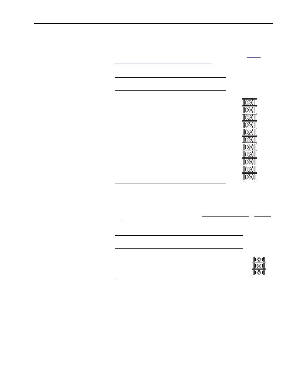
Terminal Blocks
The following tables list the connections on the Ultra5000 230V drive
(3 kW) power (TB1) and the shunt (TB2) terminal blocks.
to Wiring Power Connections on page 3-14
for additional information.
Terminal Block 1 (TB1) Locations
(2098-IPD-030-xx)
U (Motor)
2
V (Motor)
2
W (Motor)
2
Motor Case Ground
DC Bus+
1
DC Bus-
1
L1 (Main AC)
L2/N (Main AC)
Safety (Earth) Ground
L1 (Aux AC)
3
L2/N (Aux AC)
3
1
Do not connect an external I/O power supply to the DC bus. The DC+ and DC- terminals
connect directly to the power bus of the drive.
2
Ensure motor power is wired with proper phasing relative to the motor terminals. On some
motors, the motor leads may be labeled R, S, and T which correspond to U, V, and W.
3 The auxiliary AC power inputs require dual element time delay (slow acting) fuses to
accommodate inrush current. Refer to the section
for the inrush current on the auxiliary AC power input.
Shunt Terminal Block 2 (TB2) Locations
(2098-IPD-030-xx)
1 - Common Terminal for External or Internal Shunt
1
2 - Internal Shunt Terminal
1
3 - External Shunt Terminal
1
1
A jumper, selecting the internal shunt, is factory installed between terminals 1 and 2. Remove the jumper for
applications requiring an external shunt.
Refer to External Shunt Kits on page C-4
for information about available external shunt kits.