Rockwell Automation 2098-IPD-xxx Ultra5000 Intelligent Positioning Drives Installation Manual User Manual
Page 78
Publication 2098-IN001E-EN-P — April 2002
3-18
Connecting Your Ultra5000
5. Tighten each terminal screw to the appropriate torque value.
6. Gently pull on each wire to make sure it does not come out of its
terminal. Re-insert and tighten any loose wires.
7. To connect the motor power cable:
Ultra5000 Drives:
Terminal Block Torque Values:
2098-IPD-005xx, -010-xx, and -02-xx
IMPORTANT
The DC bus connections should not be used for
connecting multiple drives together. Contact your
Allen-Bradley representative for further assistance if
the application may require DC power connections.
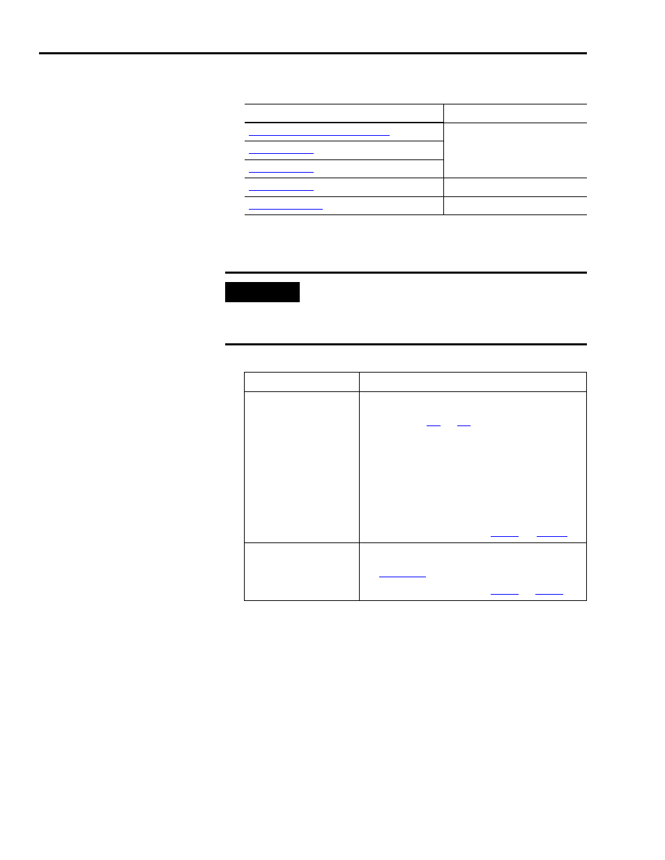
If your motor is:
Then:
F-Series, H-Series,
MP-Series, N-Series,
W-Series, or
1326AB-Bxxxx-M2L
or -S2L
1. Remove the two screws securing the cable
shield clamp on the Ultra5000 drive (refer
to figures
for the cable clamp
location on your Ultra5000 drive).
2. Place the cable within the clamp and
replace the screws (do not tighten).
3. Position the exposed portion of the cable
braid directly in line with the clamp.
4. Tighten the screws with a torque of 0.9-1.1
Nm (8.0-10.0 lb-in.).
5.
Continue with optional
.
Y-Series
1. Connect the 152.4 mm (6.0 in.) termination
wire to the closest earth ground (refer to
for pigtail location).
2. Continue with optional
.