Grounding for ultra5000 ce requirements – Rockwell Automation 2098-IPD-xxx Ultra5000 Intelligent Positioning Drives Installation Manual User Manual
Page 134
Publication 2098-IN001E-EN-P — April 2002
B-22
Interconnect Diagrams
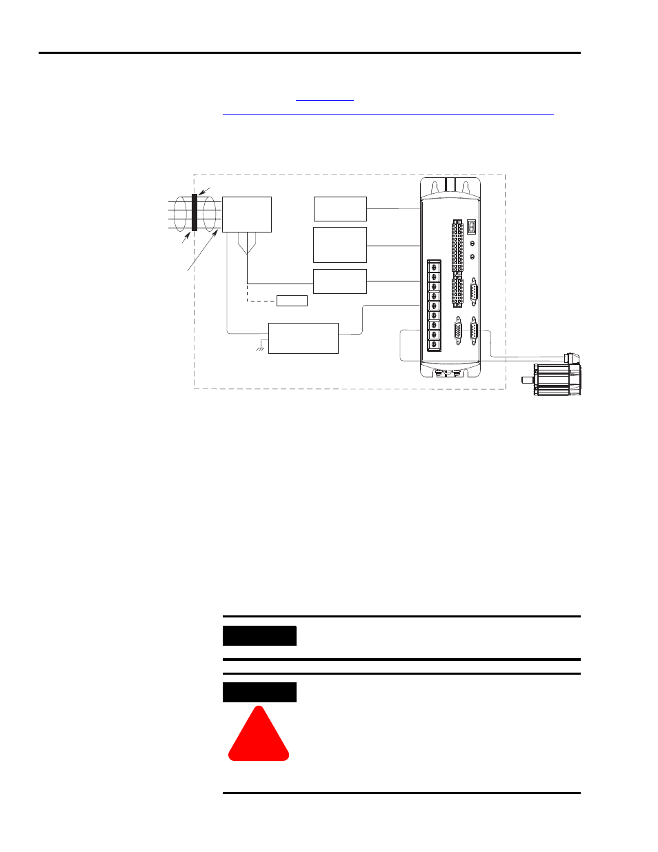
Grounding for Ultra5000 CE
Requirements
This section provides information to assist you in complying with CE
requirements.
briefly outlines Ultra5000 CE requirements.
Refer to Complying with European Union Directives on page 1-1
information on how to determine compliance of specific products.
Figure B.20
Ultra5000 CE Requirements
1
Mount the filter as close to the Ultra5000 as possible. If the distance exceeds 600 mm (2.0 ft), use a strap (greater in
width than length) rather than a wire, to connect the ground between the Ultra5000 and the filter. This is particularly
important for attenuation of higher frequency emissions (5-30 MHz).
Shield or separate the wires connecting the AC power to the filter from other power cables (e.g., connections between
the Ultra5000 and the filter, motor power cable, etc.). The best method of achieving this is to mount the filter near
where the AC power enters the enclosure. If the connections are not separated from each other, the EMI on the
Ultra5000 side of the filter can couple over to the source side of the filter, thereby reducing or eliminating the filter’s
effectiveness. The coupling mechanism can radiate or allow stray capacitance between the wires.
Filters need to be on all lines for filtering to be effective. When multiple power cables enter an enclosure, an unfiltered
line can contaminate a filtered line.
Bond the filter and the Ultra5000 to a grounded conductive surface (the enclosure) to establish a high frequency (HF)
connection. To achieve the HF ground, the contact surface interface between the filter, Ultra5000, and the enclosure
should be free from paint or any other type of insulator.
2
The filter shown is sized for one Ultra5000. Equivalent filters may be used for multiple units. Size the filter following the
manufacturers recommendations.
3
Ground bar is customer-supplied item.
4
Clamp motor power cable shield for EMC termination.
Note 1
Note 1
E
Note 2
Note 2
Note 3
Note 3
Note 4
Note 4
Ground Conduit to Enclosure
Filtered Conductors
Conduit Clamp
Single- or Three-Phase
Mains with
Ground
User Supplied
Discrete I/O
User Supplied
or Internal 24V
Power Source
Single-Phase
Discrete I/O
Unfiltered
Conductors
Enclosure
Enclosure
Bonded Cabinet
Ground Bus
Motor
IMPORTANT
All AC power in the cabinet must be filtered to
reduce EMI.
ATTENTION
!
High voltage exists in AC line filters. The filter must
be grounded properly before applying power. Filter
capacitors retain high voltages after power removal.
Before handling the equipment, voltages should be
measured to determine safe levels.
Failure to observe this precaution could result in
personal injury.