Figure – Rockwell Automation 2098-IPD-xxx Ultra5000 Intelligent Positioning Drives Installation Manual User Manual
Page 22
Publication 2098-IN001E-EN-P — April 2002
1-8
Installing Your Ultra5000
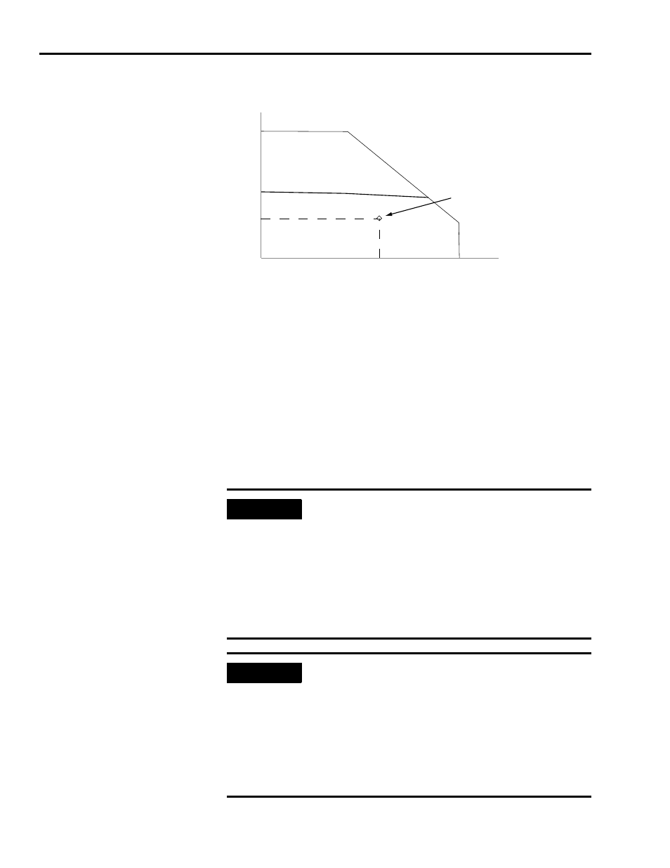
Figure 1.2
Transformer Sizing Based on Speed/Torque Data for Single Phase System
The formula and calculation are:
Definitions:
kW = power or real power
KVA = apparent power
Transformer KVA rating = (Sum of average output power of each axis) x 2.0.
IMPORTANT
Calculations are multiplied by a factor to compensate
for the power and loss elements within a power
system.
•A factor of 2.0 is used with a single phase system.
•A factor of 1.5 is used with a three phase system.
This factor minimizes the effects of the secondary
line voltage sagging in the transformer during peak
current periods.
IMPORTANT
If you are using the Rockwell Automation/
Allen-Bradley system sizing program, the average
speed and average torque data has already been
calculated and can be used in the equation. If you
are not sure of the exact speed and torque in your
application, another approach is to look at the
speed/torque curve for your Ultra5000/motor
combination and use the values for the worst case
continuous speed and torque.
TORQUE (lb-in)
3200 rpm
SPEED (RPM)
23.0 lb-in
Application
Operating Point
KVA
Speed RPM
(
) Torque lb in
–
(
)
×
63 025
,
--------------------------------------------------------------------------------
746Watts
HP
------------------------
×
KVA
1000Watts
---------------------------
Ч
2.0
Ч
=
KVA
3200rpm
23.0lb
in
–
×
42 250
,
-------------------------------------------------------
=
TransformerSize
1.75KVA
=