Rockwell Automation 2098-IPD-xxx Ultra5000 Intelligent Positioning Drives Installation Manual User Manual
Page 77
Publication 2098-IN001E-EN-P — April 2002
Connecting Your Ultra5000
3-17
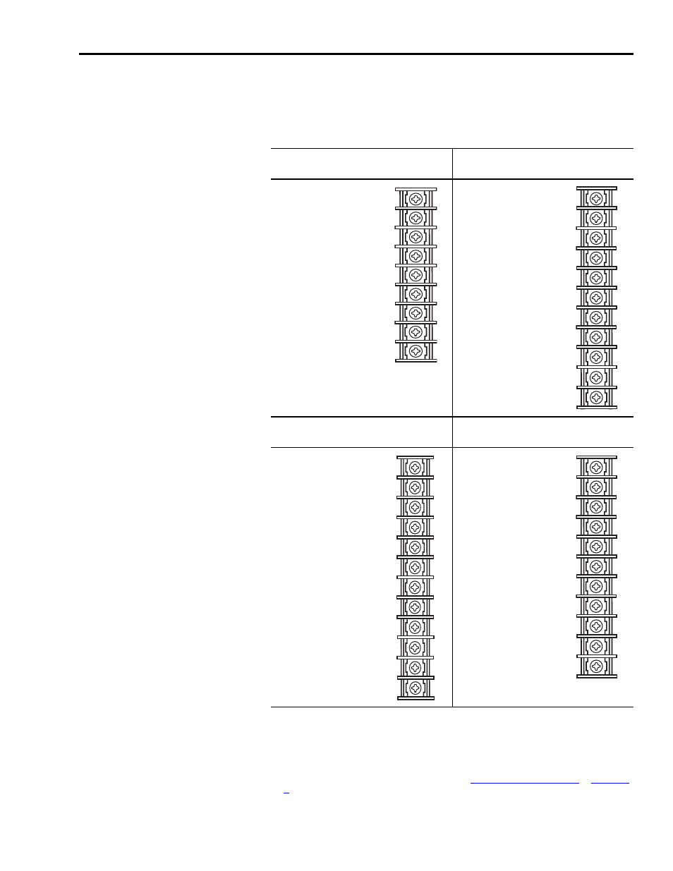
4. Using a screw driver, loosen the screw for each of the terminal
locations and attach wires as shown in the table below. Refer to
Appendix B for the power wiring diagram for your Ultra5000
drive.
Terminal Block (TB) Locations
(2098-IPD-005xx, -010-xx, -020-xx)
Terminal Block 1 (TB1) Locations
(2098-IPD-030-xx)
DC Bus+
1
U
(Motor)
2
DC Bus-
1
V
(Motor)
2
L1 (Main AC)
W (Motor)
2
L2/N (Main AC)
Motor Case Ground
Safety (Earth) Ground
DC Bus+
1
U (Motor)
2
DC
Bus-
1
V (Motor)
2
L1 (Main AC)
W (Motor)
2
L2/N (Main AC)
Motor Case Ground
Safety (Earth) Ground
L1 (Aux AC)
3
L2/N (Aux AC)
3
Terminal Block 1 (TB1) Locations
(2098-IPD-075-xx and -150-xx)
Terminal Block Locations
(2098-IPD-HVxxx-xx)
U (Motor)
2
DC
Bus+
1
V (Motor)
2
DC
Bus-
1
W (Motor)
2
W
(Motor)
2
Motor Case Ground
V (Motor)
2
DC Bus+
1
U
(Motor)
2
DC Bus-
1
Ground (Motor and Earth)
L1 (Main AC)
L3 (Main AC)
L2 (Main AC)
L2 (Main AC)
L3 (Main AC)
L1 (Main AC)
Safety (Earth) Ground
L1 (Aux AC)
3
L1 (Aux AC)
3
L2 (Aux AC)
3
L2/N (Aux AC)
3
1
Do not connect an external I/O power supply to the DC bus. The DC+ and DC- terminals
connect directly to the power bus of the drive.
2
Ensure motor power is wired with proper phasing relative to the motor terminals. On some
motors, the motor leads may be labeled R, S, and T which correspond to U, V, and W.
3 The auxiliary AC power inputs require dual element time delay (slow acting) fuses to
accommodate inrush current. Refer to the section
for the inrush current on the auxiliary AC power input.