Analog outputs, Analog outputs -24 – Rockwell Automation 2098-IPD-xxx Ultra5000 Intelligent Positioning Drives Installation Manual User Manual
Page 50
Publication 2098-IN001E-EN-P — April 2002
2-24
Ultra5000 Connector Information
Analog Outputs
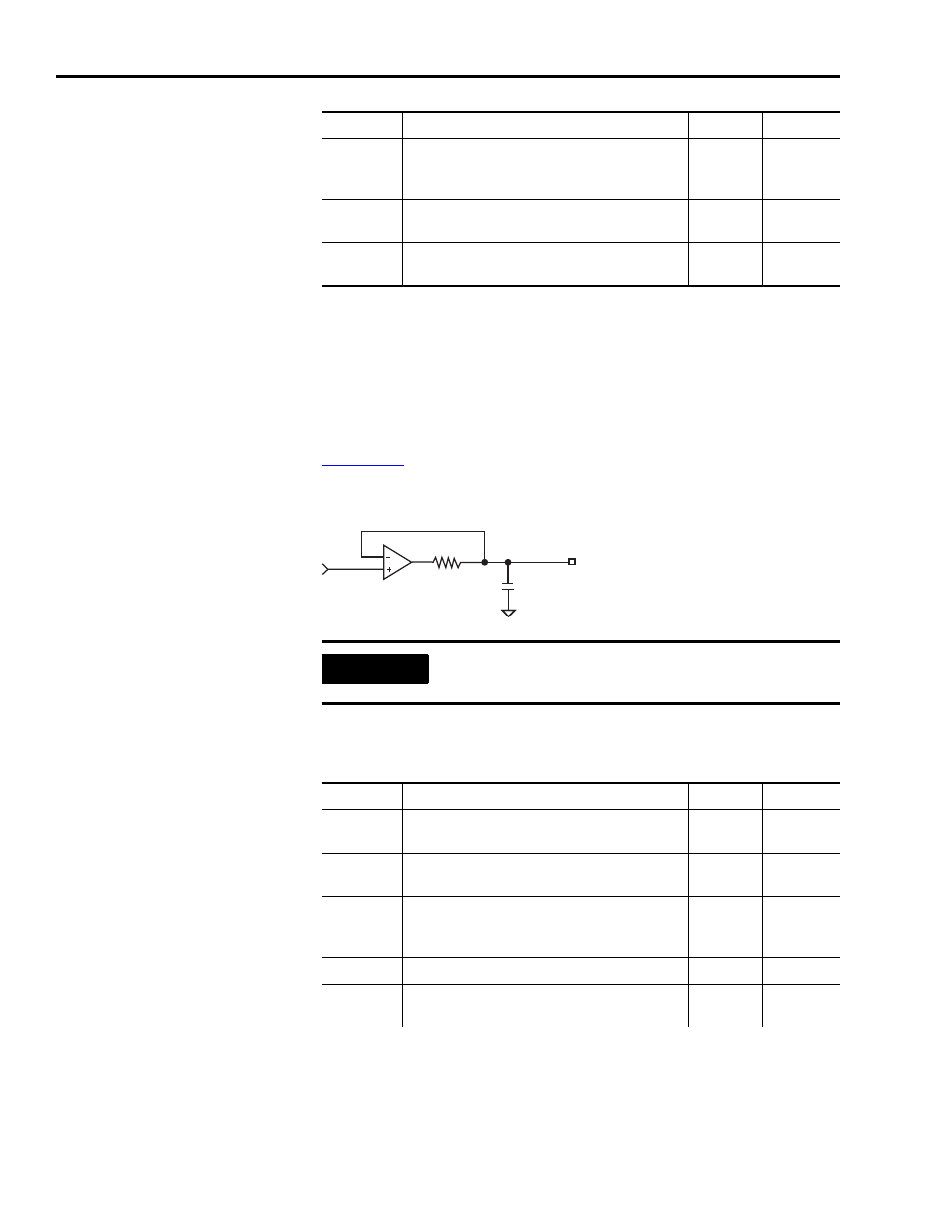
There are two analog outputs to use as needed. A 12 bit D/A
converter generates an analog representation of the digital command
value. The analog outputs are set to zero after the power comes up.
shows the configuration of the analog outputs.
Figure 2.12
Analog Output Configuration
The following table provides a description of the analog output
specifications.
Offset Error
Deviation from the correct value expected from
analog-to-digital conversion when 0V is applied
to the input.
—
50 mV
Gain Error
Deviation of the transfer function from unity
gain, expressed in a percent of full scale.
—
1%
Propagation
Delay
Delay from the input to the firmware-accessible
registers.
—
100 mS
IMPORTANT
Output values can vary during power-up until the
specified power supply voltage is reached.
Parameter Description
Minimum Maximum
Resolution
Number of states that the output signal is
divided into, which is 2(to the number of bits).
12 Bits
—
Output
Current
Current capability of the output.
-2 mA
+2 mA
Output
Signal
Range
Range of the output voltage.
-10V
+10V
Offset Error
Deviation when the output should be at 0V.
—
50 mV
Gain Error
Deviation of the transfer function from unity
gain, expressed in a percent of full scale.
—
1%
Parameter Description
Minimum Maximum
1k
Ω
1000pF
AOUT