Understanding ultra5000 controller functions, Ultra5000 block diagram, Understanding ultra5000 controller functions -2 – Rockwell Automation 2098-IPD-xxx Ultra5000 Intelligent Positioning Drives Installation Manual User Manual
Page 28: Ultra5000 block diagram -2
Publication 2098-IN001E-EN-P — April 2002
2-2
Ultra5000 Connector Information
Understanding Ultra5000
Controller Functions
This section provides a short overview of the Ultra5000.
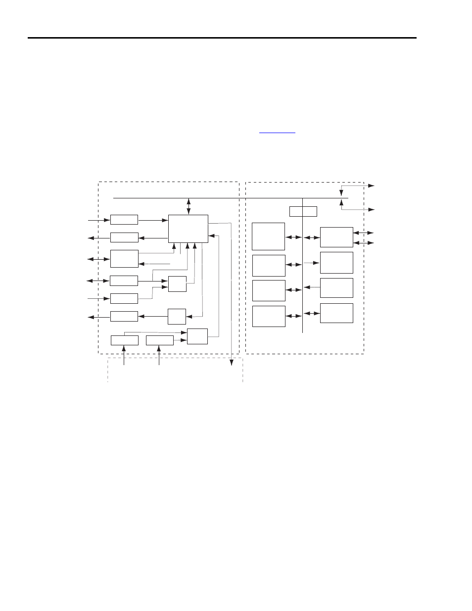
Ultra5000 Block Diagram
The Ultra5000 uses a two-stage circuit card solution with the capability
of adding two additional option cards. The first stage is the processor
circuit board and the second stage handles I/O connections including
a power module interface.
depicts the stages and the
interfaces.
Figure 2.1
Block Diagram of Ultra5000 Controller Functions
Interface
Interface
Interface
Interface
Interface
Interface
Interface
Interface
Interface
Interface
Interface
Interface
Interface
Interface
Interface
Interface
Interface
Interface
Digital Inputs
Digital Inputs
Digital Outputs
Digital Outputs
Auxiliary Encoder Inputs
Auxiliary Encoder Inputs
Motor Encoder Outputs
Motor Encoder Outputs
Motor Encoder
Motor Encoder
Analog Inputs
Analog Inputs
Analog Outputs
Analog Outputs
Gate Array
Gate Array
Quad
Quad
ADC
ADC
Dual
Dual
DAC
DAC
Quad
Quad
ADC
ADC
POWER MODULE
POWER MODULE
Bus Voltage
Bus Voltage
Input
Input
Current
Current
Inputs
Inputs
PWM
PWM
Outputs
Outputs
I/O CARD
I/O CARD
512Kx8
512Kx8
Low Speed
Low Speed
Flash
Flash
Memory
Memory
256Kx32
256Kx32
System Flash
System Flash
Memory
Memory
128Kx32
128Kx32
High Speed
High Speed
SRAM
SRAM
64Kx8
64Kx8
Non-Volatile
Non-Volatile
SRAM
SRAM
Serial
Serial
Interface
Interface
7-Segment
7-Segment
LED
LED
Display
Display
Rotary DIP
Rotary DIP
Switches
Switches
TMS320C32
TMS320C32
DSP
DSP
Serial Port 1
Serial Port 1
Serial Port 2
Serial Port 2
Option Card Port 1
Option Card Port 1
Option Card Port 2
Option Card Port 2
PROCESSOR CARD
PROCESSOR CARD