Test processor transition modules, Test processor transition modules 74 – MTS Model FlexTest SE User Manual
Page 74
Models FlexTest® IIm/GT/SE Controller Hardware
Test Processor Transition Modules
Installation
74
Test Processor Transition Modules
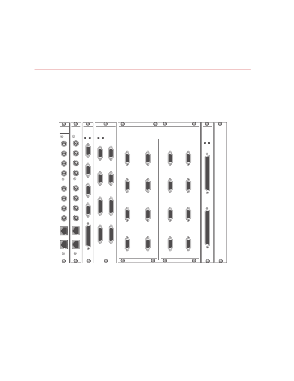
Transition modules are screwed into the back of the test processor chassis. Each
rear-panel transition module corresponds to a plug-in module (or plug-in module
mezzanine card) installed in the front of the chassis.
Transition modules interface with the other test components via connectors for
external digital, analog, and communication cables.
Transition Modules (Model 498.22 Chassis Rear Panel shown)
J3C
Sta 3
Intlk
J4
497
Hyd
J6
I/O
J5
497
Intlk
J3D
Sta 4
Intlk
J3A
Sta 1
Intlk
J3B
Sta 2
Intlk
498
SYSTEM
DIGITAL I/O
498
DIGITAL I/O
TRANSITION
MODULE
J4 OUT
+5V +12V
J3 IN
J7
I/O
+5V +12V
1 - 2
DIGITAL I/O ACCESS PANEL
DIGITAL IN1-16
DIGITAL OUT1-16
Digital Input
Channels
3 - 4
5 - 6
7 - 8
9 - 10
11 - 12
13 - 14
15 - 16
1 - 2
3 - 4
5 - 6
7 - 8
9 - 10
11 - 12
13 - 14
15 - 16
Digital Output
Channels
J50A
J50B
J50C
498
RS-485
Transition
Module
J50D
J7
+12V +5V
J11
(CH 1-4)
J12
(CH 5-8)
498
ANALOG
OUT
CH 1
CH 2
CH 3
CH 4
CH 5
CH 6
CH 7
CH 8
J11
(CH 1-4)
J12
(CH 5-8)
498
INPUT
FILTER
CH 1
CH 2
CH 3
CH 4
CH 5
CH 6
CH 7
CH 8