Model 497.05 hydraulic control panel, Model 497.05 hydraulic control panel 71, J15a–j17d – MTS Model FlexTest SE User Manual
Page 71: J28a–j28d, J41 and j42, J51 and j52
Model 497.05 Hydraulic Control Panel
Models FlexTest® IIm/GT/SE Controller Hardware
Installation
71
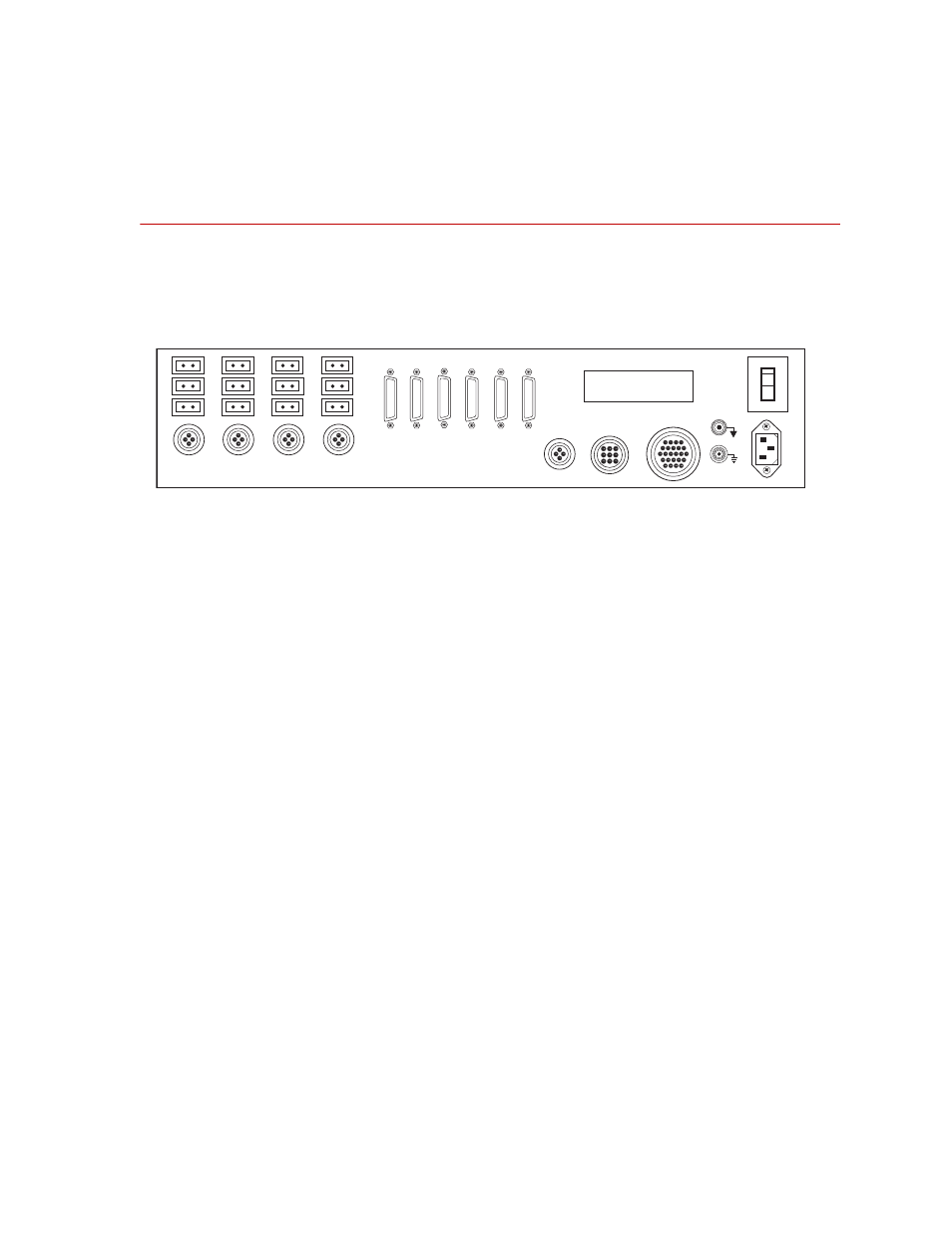
Model 497.05 Hydraulic Control Panel
The rear panel connectors of the hydraulic control panel are cabled to the
hydraulic components of your system. The connectors also interface with the
Model 497.01 Analog Chassis and Model 498.22 Test Processor chassis.
Hydraulic Control Panel
J1
The 497.05 contains the power supply for a Model 497.01 Analog Chassis.
Connect your 497.01 Analog Chassis to J1.
J8
This connector communicates hydraulic status with the Model 498.22 Test
Processor chassis.
J9
This connector is not used in a standard FlexTest IIm system.
J15A–J17D
Each HSM channel has a set of three user defined interlock inputs (Interlock 1,
Interlock 2, and Shutdown). These inputs can be configured to monitor contact
closure or to accept logic level inputs.
J25
This connector controls the hydraulic power supply (HPS).
J26
This connector accommodates a remote Emergency Stop switch.
J28A–J28D
These connectors control up to four hydraulic service manifolds (HSMs).
J41 and J42
These connectors create a serial communications loop between all of the chassis
in your system.
J51 and J52
These connectors create an interlock communications loop with the other chassis
in your system.
I
O
J41
Com In
J8
Hyd Enab
J15C
J16C
J17C
J15B
J16B
J17B
J15A
J16A
J17A
J1
497.01 Power
J26
Remote E-Stop
J25
HPS
J52
Intlk Out
J51
Intlk In
J42
Com Out
J9
Mstr/Slv
J28D
J15D
J16D
J17D
J28C
J28B
J28A