Emergency stop connections, Emergency stop connections 129, Emergency stop output – MTS Model FlexTest SE User Manual
Page 129: Emergency stop input, Cable specifications
Emergency Stop Connections
Models FlexTest® IIm/GT/SE Controller Hardware
FlexTest GT Controller Connections
129
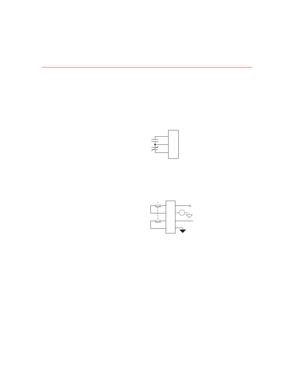
Emergency Stop Connections
Connectors J23 E-STOP Out and J24 E-STOP In are located on the Model
493.73 HPU transition board. The Emergency Stop switch and signal are part of
a controller-wide interlock system.
Emergency
stop output
Connector J23 E-STOP Out provides an output to external devices when an
emergency stop signal is generated. The inactive status is shown in the figure.
Emergency
stop input
Connector J24 E-STOP In accommodates an external emergency stop switch.
As shown, several connectors maintain the continuity of the emergency stop
interlock.
Cable specifications
J23 E-STOP Out is a 9 pin type D male connector
•
9-contact type D female EMI connector
•
Cable—24 AWG, 10 conductor with overall foil shield, (Carol C0745 or
equivalent) with drain wire connected to metallized plastic backshell to the
chassis.
1
2
3
Emergency
Stop
J23
To
External
Devices
From
Chassis
+24 V
13
8
7
5
E-Stop
Signal
J24
E-Stop
Relay
External
E-Stop