Vmebus modules, Vmebus modules 43 – MTS Model FlexTest SE User Manual
Page 43
VMEbus Modules
Models FlexTest® IIm/GT/SE Controller Hardware
Installation
43
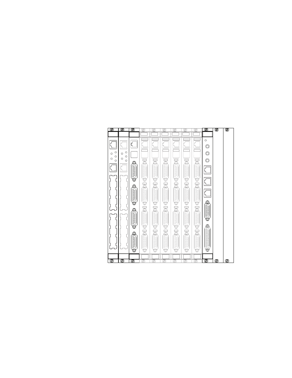
VMEbus Modules
The VMEbus compatible modules should be installed in the front panel chassis
slots according to the following guidelines.
•
The processor module(s) must be located in the first (and second) slots.
•
The GRESIII module (if used) should be located in slot 10. It may also be
located in slot 2 if a second processor is not used.
•
I/O carrier modules and/or ADDA II modules can be installed in slots 3 to
10. Install a module in slot 3 and any additional modules to the right of it.
BFL
CPU
PMC
ABT
RST
J6 I/O
J7 I/O
493.40
I/O Carrier
J3 Service
Shunt Cal
J4 I/O
J5 I/O
m
CLOCK OUT
EVENT OUT
J3 IN
J6 STATION
J7 SERIAL
EVENT IN
J4 OUT
J5 DEBUG
+12V
1
2
3
4
5
6
7
8
9
10
BFL
CPU
PMC
ABT
RST
J6 I/O
J7 I/O
J6 I/O
J7 I/O
J6 I/O
J7 I/O
J6 I/O
J7 I/O
J6 I/O
J7 I/O
J6 I/O
J7 I/O
493.40
I/O Carrier
J3 Service
Shunt Cal
J4 I/O
J5 I/O
m
493.40
I/O Carrier
J3 Service
Shunt Cal
J4 I/O
J5 I/O
m
493.40
I/O Carrier
J3 Service
Shunt Cal
J4 I/O
J5 I/O
m
493.40
I/O Carrier
J3 Service
Shunt Cal
J4 I/O
J5 I/O
m
493.40
I/O Carrier
J3 Service
Shunt Cal
J4 I/O
J5 I/O
m
493.40
I/O Carrier
J3 Service
Shunt Cal
J4 I/O
J5 I/O
m
m
498.98-2
Power PC
m
498.98-2
Power PC
m
498.71B
GRES III
Placement of
VMEbus modules in
the front panel
chassis