Connecting interlock signals to 407 controllers, Connecting interlock, Signals to 407 controllers – MTS Model FlexTest SE User Manual
Page 156: Single 407 controller interlock connections
Models FlexTest® IIm/GT/SE Controller Hardware
Connecting Interlock Signals to 407 Controllers
FlexTest GT Controller Connections
156
Connecting Interlock Signals to 407 Controllers
The Model 793 Controller monitors digital I/O interlock signals through the
Model 493.74 HSM transition module’s J43A and J43B connectors. Use these
connectors when connecting to Model 407 Controllers.
Model 493.74 HSM transition module connectors are as shown in the figure that
follows.
Interlock cabling to Model 407 Controllers depends on your system’s
configuration. There are three possible configurations:
•
Single station—one Model 407 Controller runs a single test program.
•
Multiple stations—two or more independent Model 407 Controllers each
run different test programs.
•
Master-dependent station—one master Model 407 Controller daisy-chained
with other dependent Model 407 Controllers together run a single test
program.
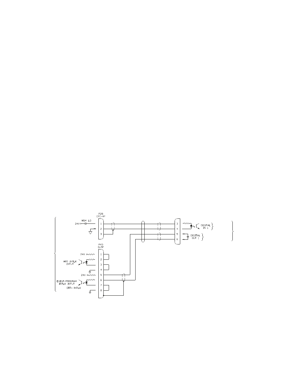
Single 407 Controller
interlock connections
The following figure shows how to cable interlocks for a single station Model
407 Controller to the Model 493.10 Chassis (via its Model 493.74 HSM
transition module). Use the specified interlock cable (PN 056-455-0xx) to make
these connections.
Run/Stop,
ActiveHigh
Hydraulic
Interlock,
ActiveLow To
407
Controller
To
493.74
HSM
Transition
Interlock Cable PN 056-455-0XX
Digital
I/O Connector
Jumper
Jumper
Jumper