Digital outputs, Cable specification – MTS Model FlexTest SE User Manual
Page 143
Digital I/O Connections
Models FlexTest® IIm/GT/SE Controller Hardware
FlexTest GT Controller Connections
143
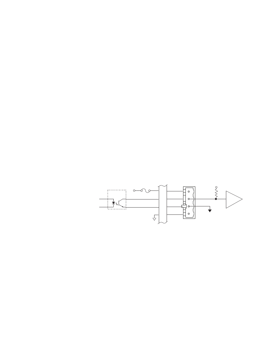
Digital outputs
Connector J4 Out provides sixteen general purpose digital outputs that can send
digital logic signals to external switches or logic devices.
•
Minimum output current drive is 6 mA. Maximum output current drive is 20
mA.
Note
The maximum output current can vary from unit to unit. The minimum
guaranteed output current is 6 mA and the maximum output current is 20
mA. You can connect the digital outputs in parallel to increase the current
drive. When connected in parallel, the station must be configured so that
all paralleled outputs are driven from the same event.
•
The output is rated for a maximum of 30 V DC.
•
Fused 12 V DC is available at pins 18 and 19.
Install a current-limiting resistor that is appropriate for the external device.
•
If an output is not used, a jumper is not needed to complete a circuit.
•
The outputs are optically isolated.
•
The outputs are triggered by the system controller.
Cable specification
The cabling information shown assumes a single cable destination (with an
overall shield). In other applications, the cable may have more than one
destination. For these applications an overall shield is not practical and non-EMI
connectors and back shells are permissible.
•
37-contact type D male EMI connector
•
Back shell–EMI metallized plastic
•
Cable–shielded twisted pairs as required (24 AWG minimum) with drain
wire(s) connected to the metallized backshell at the chassis.
18
2
21
36
J4
Ext Voltage
+CH2
-CH2
External Device
Digital I/O
Access Panel
+12
Opto-
Coupler
493.72 Digital I/O
Transition Board